


HT35X – Cross Flow Heat Exchanger
The cross flow heat exchanger is commonly used in applications such as heating, ventilating and air conditioning. It is also encountered as vehicle engine radiator.
Description
The cross flow heat exchanger is commonly used in applications such as heating, ventilating and air conditioning. It is also encountered as vehicle engine radiator.
This type of heat exchange occurs when the flow direction of the two fluids cross each other. In the HT35X, hot water flows in and out of a radiator, perpendicular to air stream, which is being pulled into the radiator by an axial fan.
The convection between the two fluids through fins surface on the radiator implements the heat exchange.
Technical Specifications
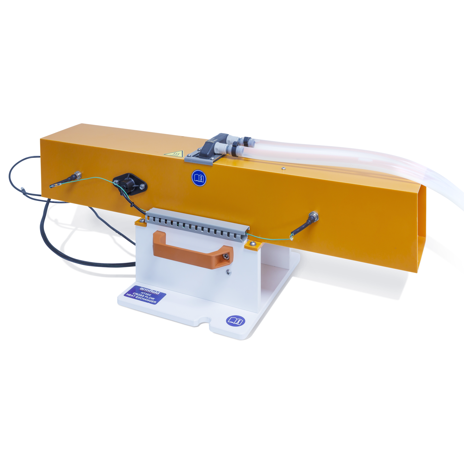
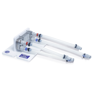
- This unit consists of a PVC rectangular duct, variable speed axial fan and a single fan radiator
- The radiator is accommodated in the middle and across the air duct
- The axial fan is located between the radiator and one edge of the duct. It can provide max air velocity of 4m/s
- The fins of the radiator are made from copper and allow a heat transfer area of 11,000mm2
- Four thermocouples measure the base unit and accessory’s input and output water as well as the air temperatures
- Quick release hot fluid connections allow rapid connection to HT30X
- The exercises proposed with the HT35X provide function of basic engineering concepts such as psychometric properties and mathematical iteration
- The HT35X software includes application of the LMTD (Log Mean Temperature Difference) method for cross flow heat exchanger as well as the effectiveness – NTU (Number of Transfer Units) method
- An air velocity sensor provides measurement of air flow inside the duct, which can be directly observed on the units software
- The HT35X software is an interactive tool for high understanding of the factors and variables involved in cross flow heat exchange
Features & Benefits
- A small scale cross flow heat exchanger system for use with the Armfield Computer Controlled Heat Exchanger Service Unit to teach the fundamentals concepts of heat transfer
- Some parts in the heat exchanger such as probes and axial fan can be easily removed for cleaning
- The HT35X enables variation of the parameters involved in the cross flow exchange process and therefore a complete analysis of the phenomena
- Thermocouples measure the inlet and outlet water from the base unit and air temperatures. The the air velocity sensor connects to the HT30X, 0-10m/s
- The air mass flow rate is derived using an air velocity sensor
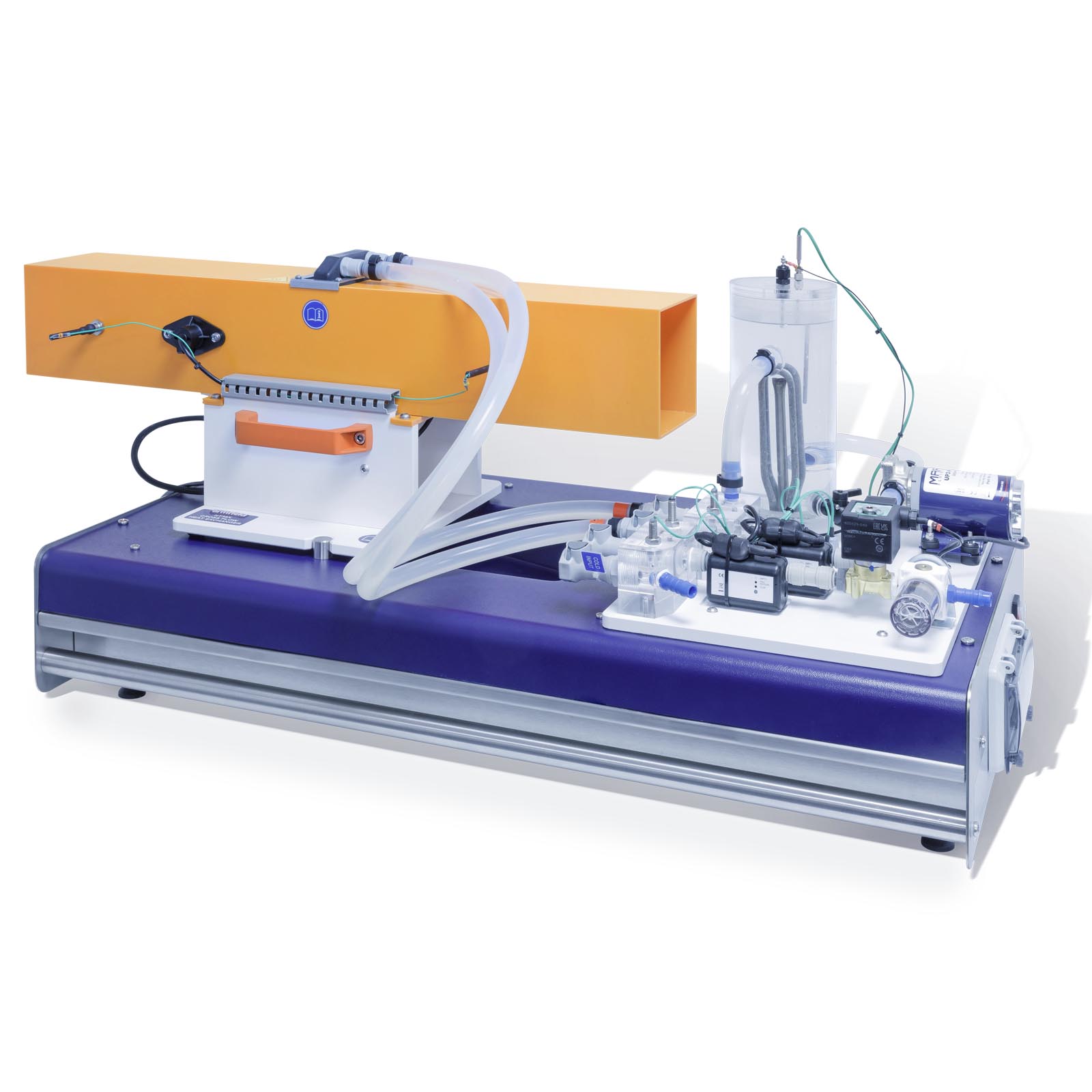
- The HT35X is mounted on a PVC baseplate which is designed to be installed on the plinth of the Computer Controlled Heat Exchanger Service Unit without the need for tools
- A comprehensive instruction manual is included

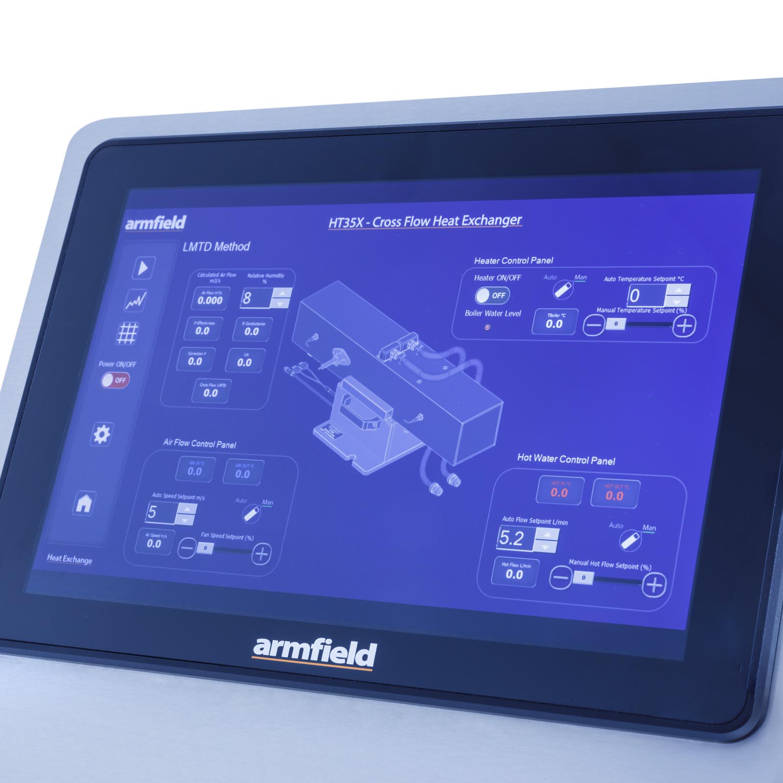
ArmBUS software is provided as standard with the HT30X for all the Armfield heat exchanger accessories. Individual programs are provided for each exchanger, and each program contains a selection of separate exercises that can be performed.
The actual details are exercise specific, but typically the following interfaces are available:
- Full Graphical User Interface (GUI) for each experiment with display screens tailored for each exercise
- All the temperatures and flow rates are displayed on a diagrammatic representation of the equipment
- Student questions and equations can be accessed individually for each exercise
- The hot-water flow rate utilises optional Manual/Automatic control to control the pump output. Manual control allows the user to select a percentage of the total power to supply to the pump. Automatic control allows the user to input the desired set point which the PID control will reach and maintain. The use of automatic control ensures the flow is stable despite changes in the viscosity of the water due to heating
- Real-time flow rate readings are displayed in L/min Sensor data is collated and calculations are displayed in a data-log, a tabulation function provided with the armBUS software. The data is in tabulated format and can be saved and accessed through a .csv file compatible with software such as Microsoft Excel
- The cold-water flow control valve utilises optional Manual/Automatic settings to control water flow from the mains. Manual control allows the user to open/close the valve between 0 and 100%. Automatic control allows the user to input the desired set point which the PID control will reach and maintain so long as the input pressure is adequate.
- The heater utilises optional Manual/Automatic control to supply power to the heater element in the boiler. Manual control allows the user to select a percentage of the total power to supply to the heater. Automatic control allows the user to select a set point (°C), and then PID control software heats the water to and maintains a set temperature
- The data from the sensors is plotted and displayed in a user-configurable graphing function of the software. It can be displayed separately from the data logging and each sensor output can be viewed independently
- Processing of measured values to obtain calculated results (this can be linked to the questions and answers to ensure student understanding, answers to equation calculations can be found as part of the datalogger output)
- HT30X Computer Controlled Heat Exchanger Service Unit
Packed and crated shipping specifications
Volume: 0.09m3
Gross weight: 6kg
Length: 0.15m
Width: 0.75m
Height: 0.40m
HT35X – Cross Flow Heat Exchanger
See HT30X for power options

