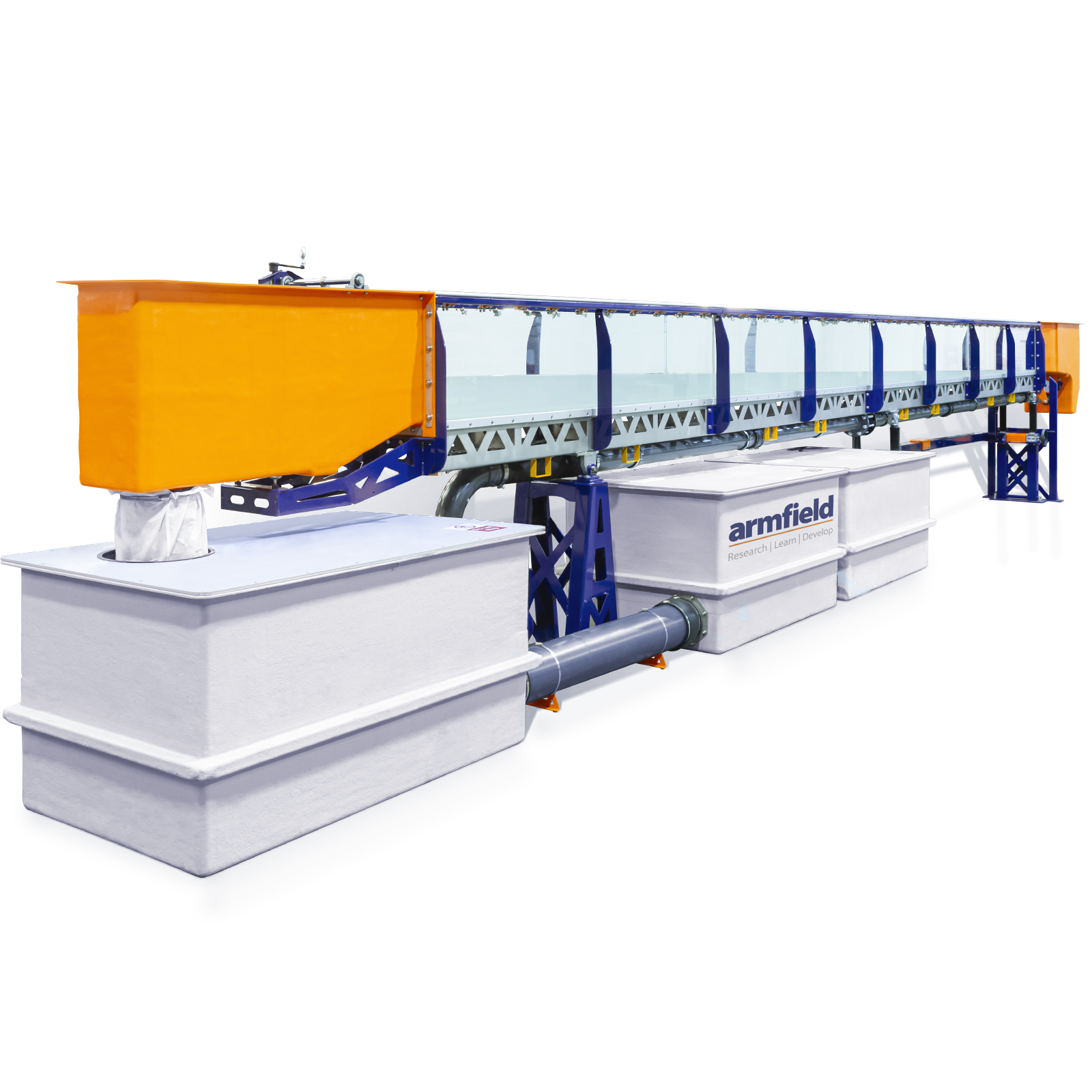
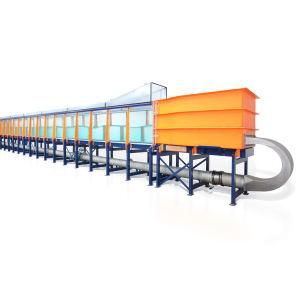
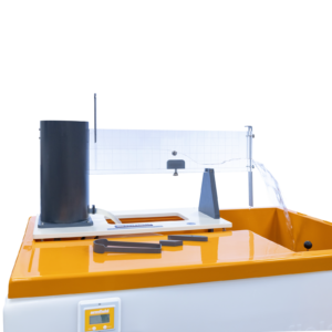
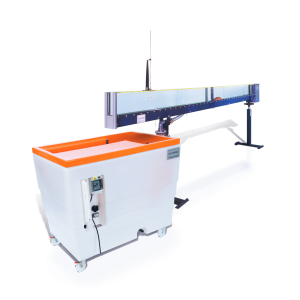
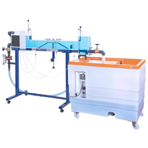
S6-MKIII Standard teaching & research flume
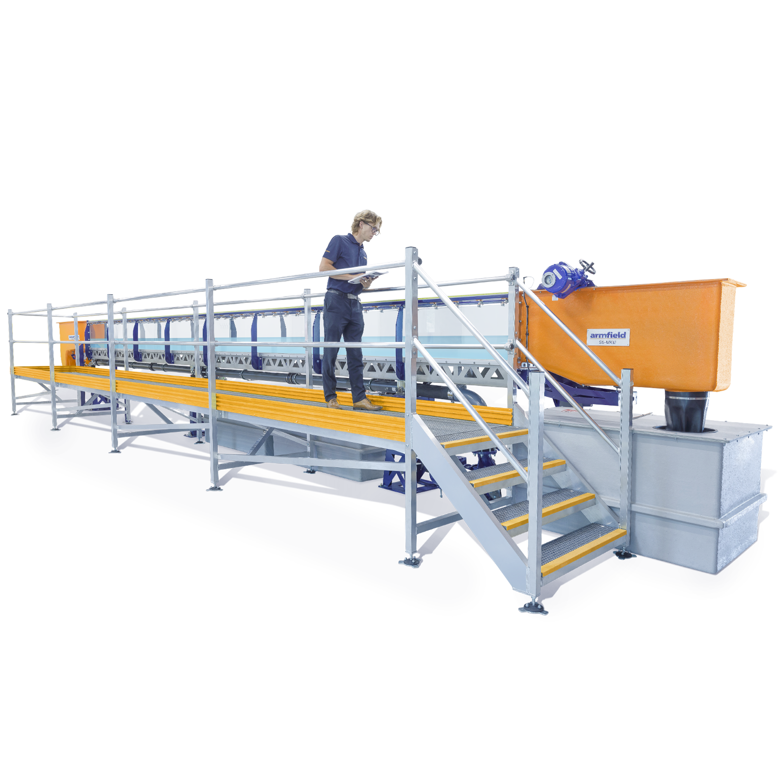
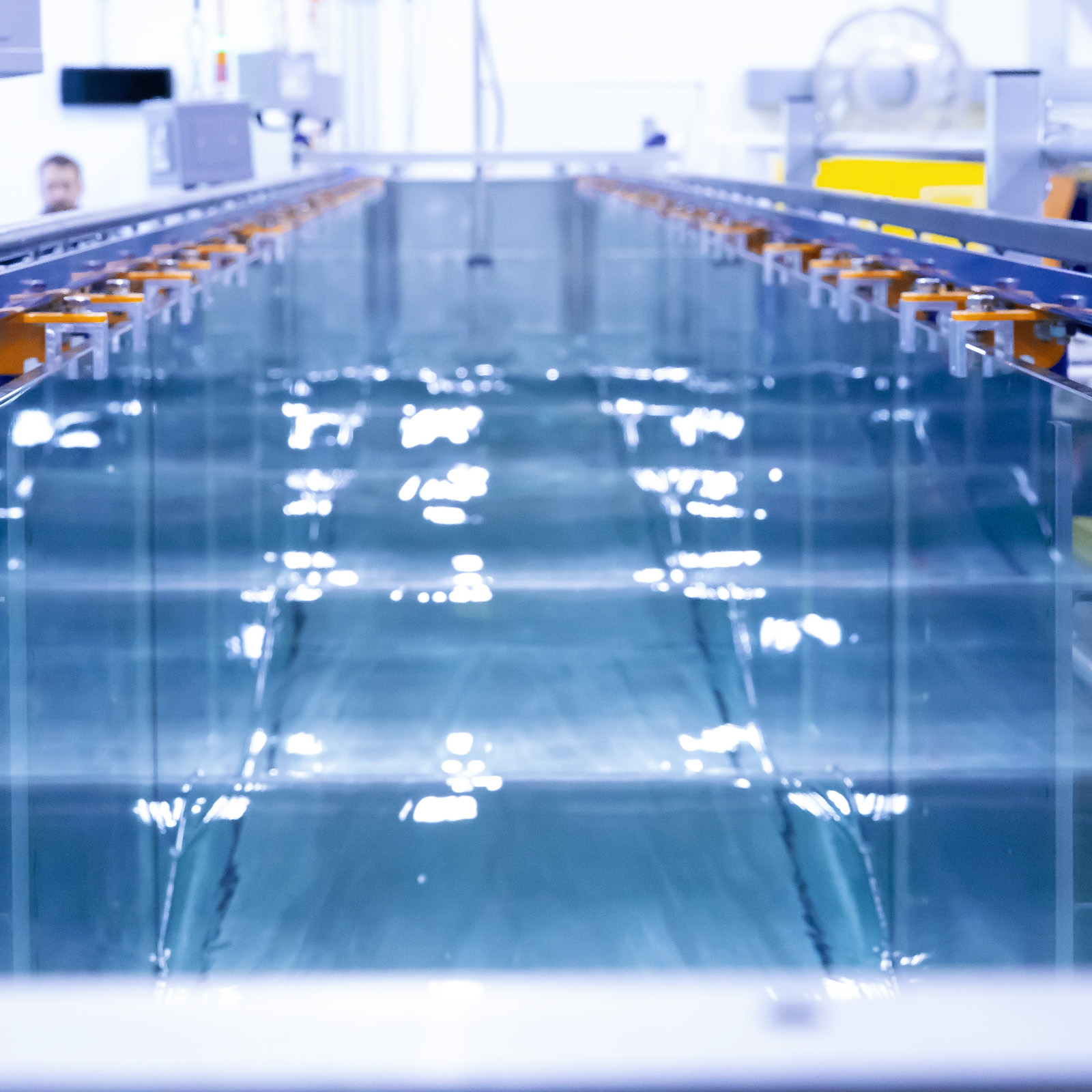
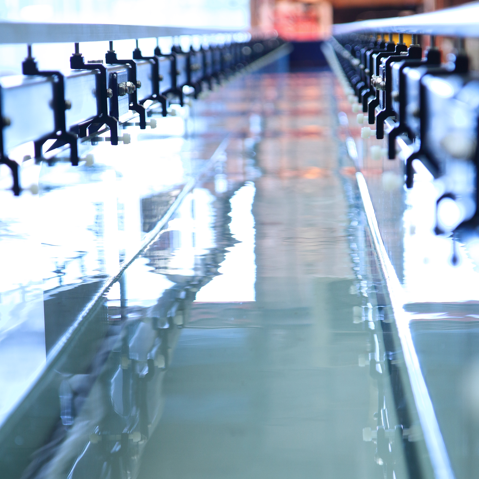
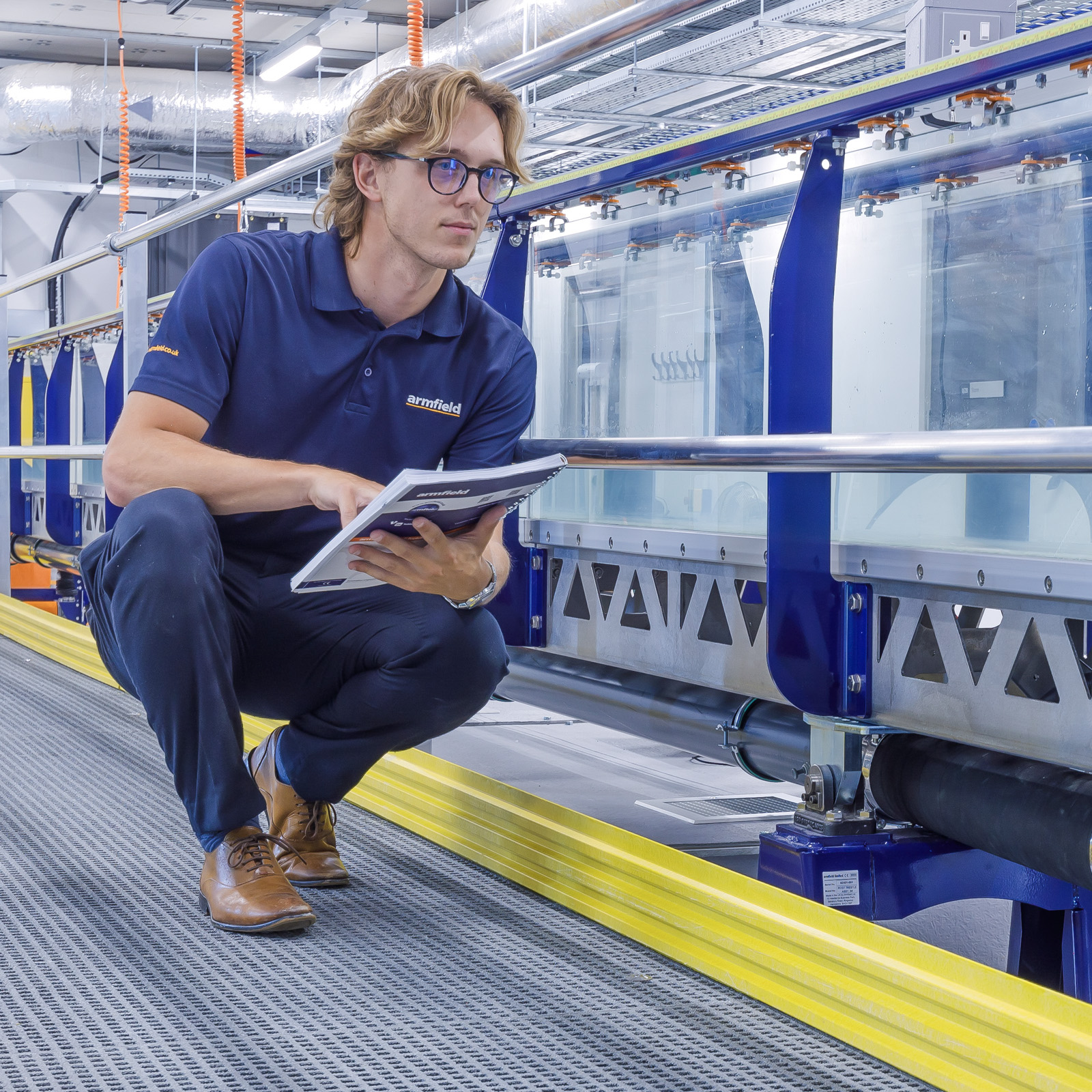
The Armfield S6-MKIII laboratory flow channel is one of the most important tools available to the hydraulics or civil engineer whether engaged in teaching basic principles or researching solutions to practical problems.
Many applications in fluid mechanics are associated with the flow of water through an open channel where the water has a free surface that is exposed to the air at atmospheric pressure.
The flumes are available in different lengths from 5 to 17.5 meters increasing in 2.5 meter increments. Armfield flumes are installed in educational and research establishments throughout the world.
Description
The Armfield S6-MKIII laboratory flow channel is one of the most important tools available to the hydraulics or civil engineer whether engaged in teaching basic principles or researching solutions to practical problems. Many applications in fluid mechanics are associated with the flow of water through an open channel where the water has a free surface that is exposed to the air at atmospheric pressure.
The flumes are available in different lengths from 5 to 17.5 meters increasing in 2.5 meter increments. Armfield flumes are installed in educational and research establishments throughout the world.
A comprehensive range of accessories, and measuring instruments is available including discharge control, wave generation and a closed loop for sediment transport studies.
- A self-contained glass sided tilting flume for fluid mechanics laboratory experiments, project work and research activities
- The flume working channel is assembled from modular sections of 2.5m length. A wide choice of standard lengths are available from 5m upwards
- The flume cross-section is 300mm wide by 450mm deep
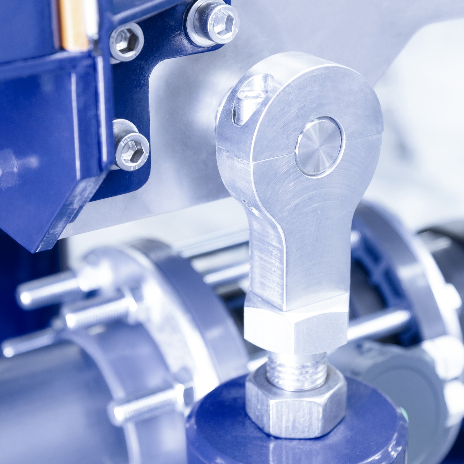
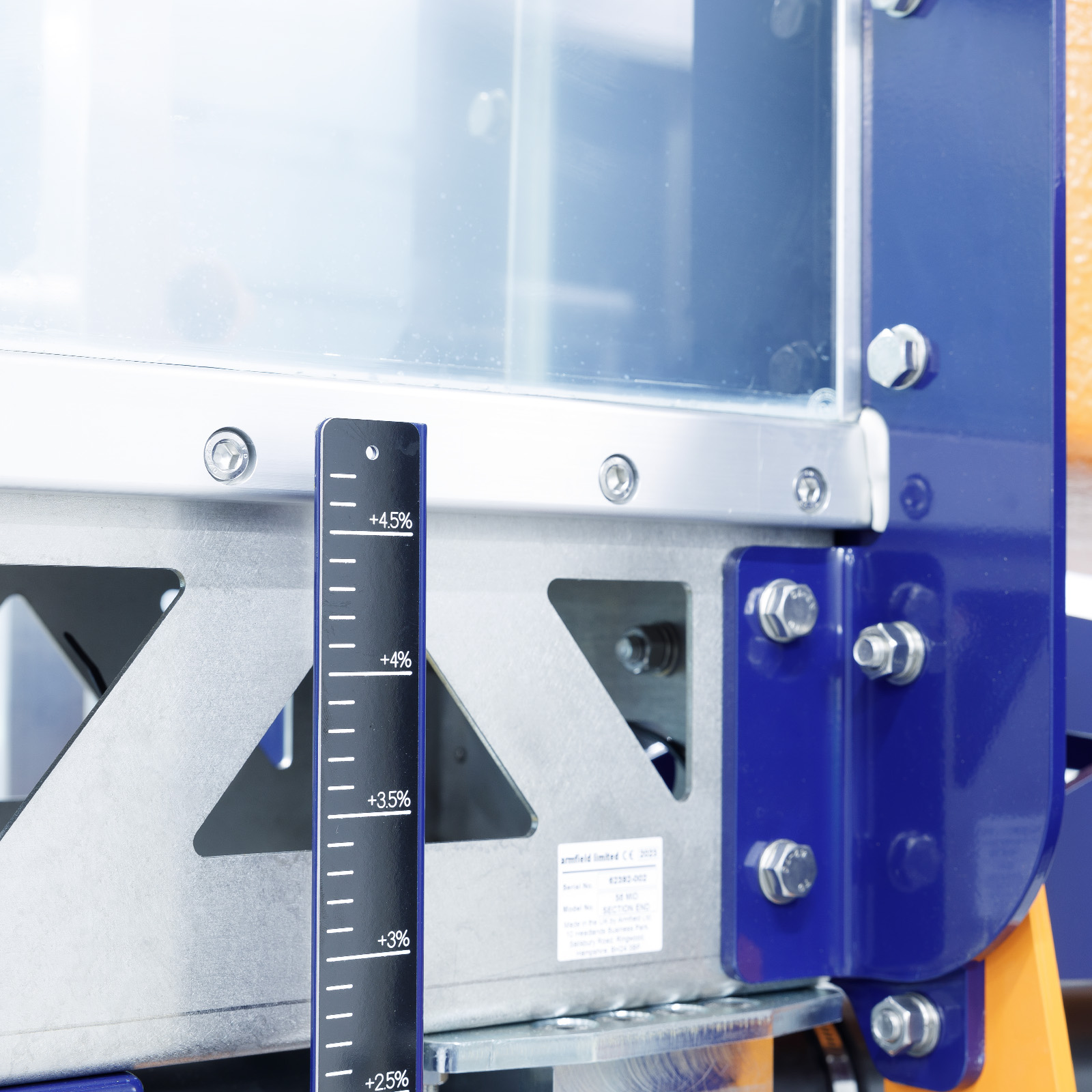
- A fabricated high precision stainless steel bed provides excellent strength and rigidity, eliminating the need for a separate under-frame.
- No adjustments other than the jacking stations are necessary in order to set up and maintain the equipment, achieving typical bed deformations better than 1mm
- Each flume incorporates a discharge tank fitted with an adjustable overshot weir and draught tube to avoid splashing and noise
- An electro-magnetic flow meter is incorporated as standard
- A comprehensive range of optional accessories and instruments is available to supplement the capabilities of the basic flume
- Closed-loop re-circulation is an option for sediment transport studies
Engineering
The most important aspect of a tilting flume is retaining the integrity of the working section. To achieve this requires an extremely rigid design which ensures almost no deflection regardless of load or tilt.
Experiments & Research
The Armfield S6-MKIII flume has been developed during 30 years of continuous production, and examples are installed in educational and research establishments throughout the world.
The flumes are available in different lengths to suit the application, short versions for basic investigations and longer versions for investigations of gradually varied flow profiles with non-uniform channel flow.
Technical Specifications
Walls: Toughened glass
Bed: Exclusively fabricated from stainless steel
End tanks: GRP (Glass Reinforced Plastic)
Sump tanks & pipework: PVC (Polyvinyl chloride) & PE (polyethylene)
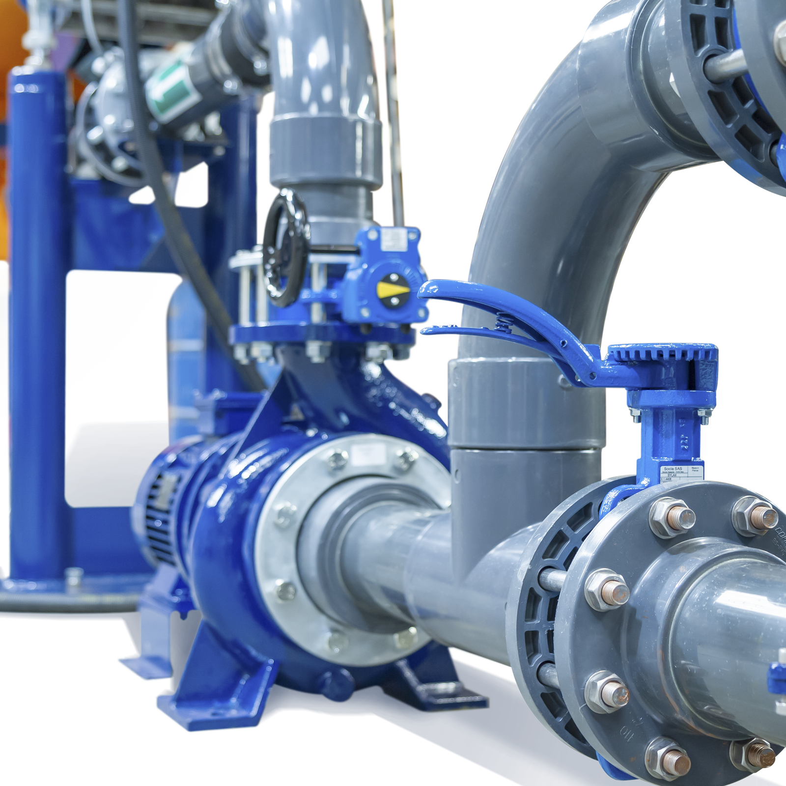
Pump: Close-coupled centrifugal
Flow regulation valve: Hand wheel operated butterfly
Tilt parameters:
+ve slope 1:40 max (1.4º)
-ve slope 1:200 max (0.28º)
Flow meter: Electro-magnetic
Maximum flow rate: 38 Litres/sec
Bed stability: 1.0mm (typical) at 400mm water depth
Side wall stability: 0.8mm (typical) at 400mm water depth
Width: 0.3m
Height: 0.45m
Features & Benefits
- Accurate for education and research
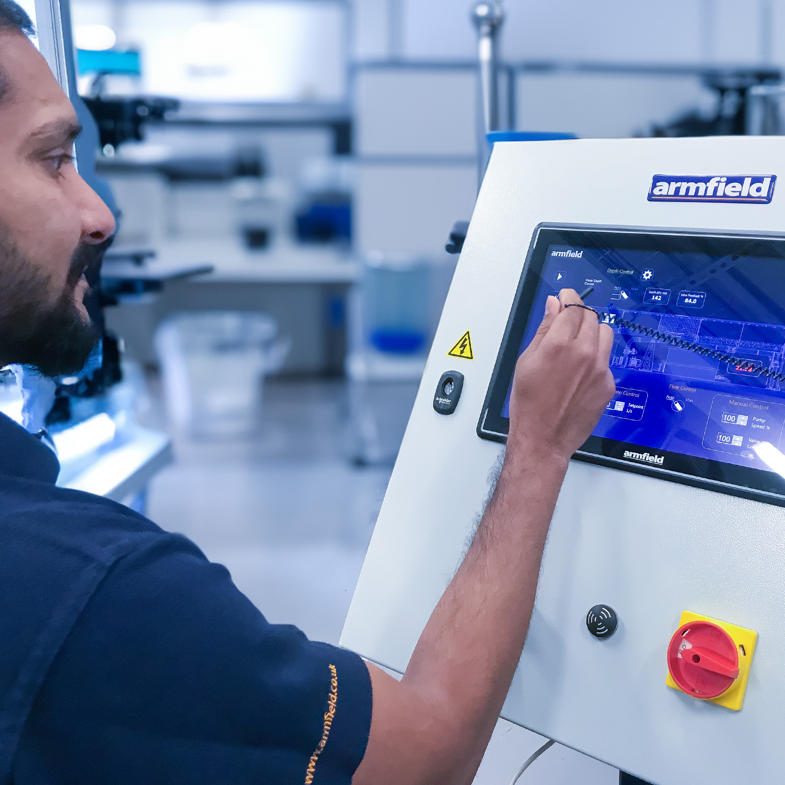
- Software supplied as standard with 15” high-definition touch screen
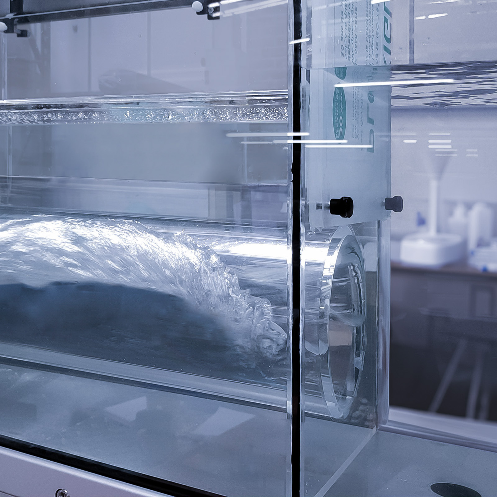
- Designed for ease of visibility:- toughened glass sides, slimline side supports and comfortable viewing height
- Modular construction supplied in pre-glazed sections for rapid and easy site assembly
- Wave generation options which can be used to propagate random or regular waves in the working section
- Optional glass base window sections for (PIV) analysis
All Armfield teaching and research flumes now come standard with a 15” high-definition touch screen control panel. The screen offers enhanced features, including automated flow control, incline feedback, and temperature measurement. Armfield’s custom software architecture provides both automated and manual control options, ensuring a full range of functionality.
Supplied Software (included)
All S6-MKIII flumes have the following as standard:
- Data acquisition
- Electromagnetic flow meter
- Variable speed stainless steel pump with inverter
- Closed loop automated flow control
- Electronic incline measurement
- Temperature measurement
- USB Data logging output
Upgrade Options
There are a full range of upgrade options for automation, allowing control over key functions such as:
- Automated Tilting
- Sediment transfer
- Wave generation
- Fully automated depth control
All data is stored for analysis, offering a comprehensive solution for research and study.
An additional option includes a 16-channel pressure sampling unit (S6-MKIII-PMP, S6-MKIII pressure sampling pack), enabling the connection of up to 16 pressure points for sampling bed pressures and other additional data.
- Characteristics of flow over rectangular thin plate weirs (Overshot)
- Characteristics of flow over profiled thin plate weirs (Overshot)
- Characteristics of flow over a sharp cornered broad crested weir
- Characteristics of flow over a streamlined broad crested weir
- Characteristics of flow over a Crump Weir
- Characteristics of flow over an Ogee Weir
- Characteristics of flow through a Venturi flume
- Characteristics of flow through a Parshall Flume
- Characteristics of flow through a WSC Flume
- Characteristics of flow over a Sill
- Characteristics of flow over a Dam Spillway
- Characteristics of flow over a Siphon Spillway
- Characteristics of flow through a self-regulating siphon
- Characteristics of Flow over a Gravel Bed
- Characteristics of flow over a Corrugated Bed
- Characteristics of flow around a Cylindrical Pile
- Characteristics of flow through a Culvert
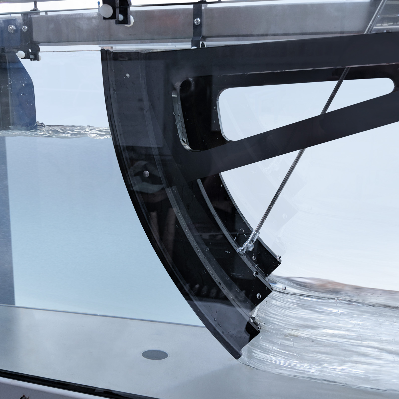
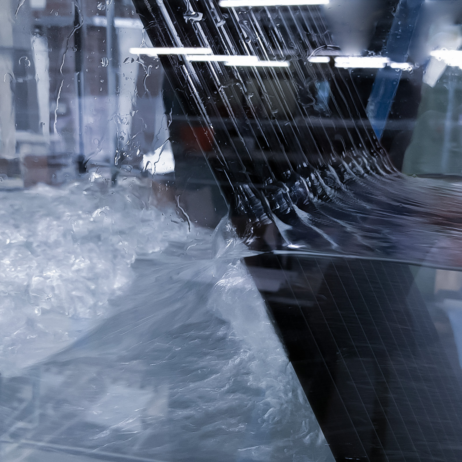
- Characteristics of flow under a Radial Gate
- Critical depth– Derivation of the Specific Energy Equation
- Discharge beneath a Sluice Gate (Undershot weir)
- Force on a Sluice Gate (Undershot weir)
- The Lift and Drag Force on Submerged Structures
- Observation of scour at Pier legs
- Head loss through a Trash Rack
- Hydraulic Jump
A comprehensive range of optional accessories, models and measuring instruments are available for selection. These provide the basis for a large number of practical experiments in open channel flow including the use and operation of regulating and gauging structures. (Non-corroding materials have been used to reduce maintenance time and increase the working life of the models).
- S6-20: Plate Weirs
- S6-21: Broad Crested Weirs
- S6-22: Venturi Flume
- S6-23: Ogee Weir & Manometer Board
- S6-24: Dam Spillway Models
- S6-25: Syphon Spillway
- S6-26: Self-regulating Syphon
- S6-27: Roughened Beds
- S6-28: Vibrating Pile
- S6-29: Lift & Drag Balance & Models
- S6-30: Pitot Tube & Manometer Board
- S6-31: Crump Weir
- S6-32: Parshall Flume
- S6-33: WSC Flume
- S6-35: Wave Generator
- S6-36: Beach
- S6-37: Zagni Flow Monitoring Systems
- S6-40: Instrument Carrier
- S6-42: Velocity Meter and Mountings
- S6-45: Random Wave Maker
- S6-46: Radial Gate
- S6-47: Set of Piers
- S6-48: Trash Rack
- S6-49: Sill
- S6-50: Culvert
- S6-MKIII-DTA-ASUITE Software Control and Data Acquisition Package
- S6-MKIII-DTA-ALITE: Data Logging and Instrumentation System
Accessories – S6-MkIII Standard flume
A comprehensive range of accessories are available for selection. These provide the basis for a large number of practical
experiments in open channel flow including the use and operation of regulating and gauging structures.
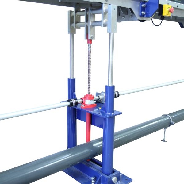
S6-MKIII-PJ: Power Jacking System
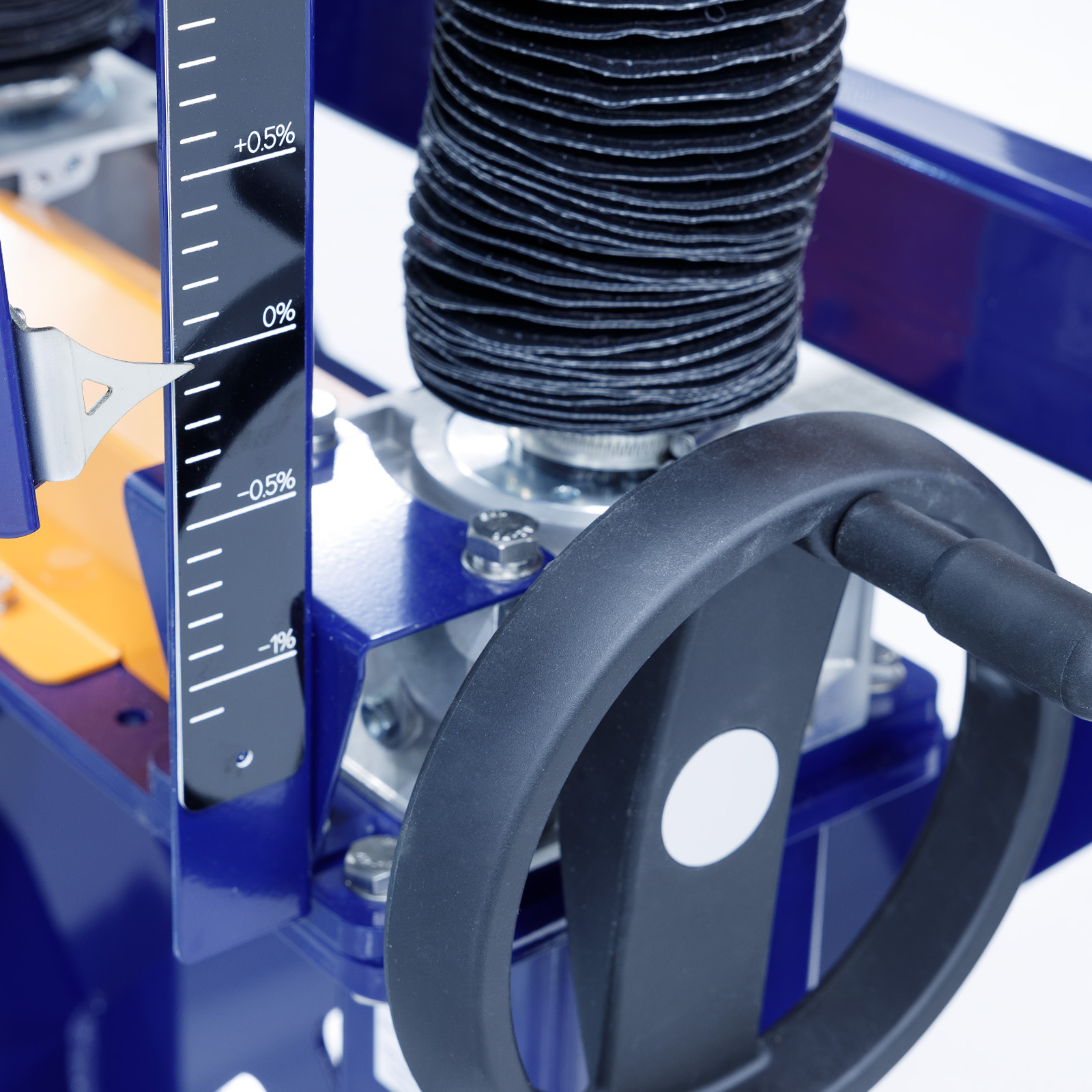
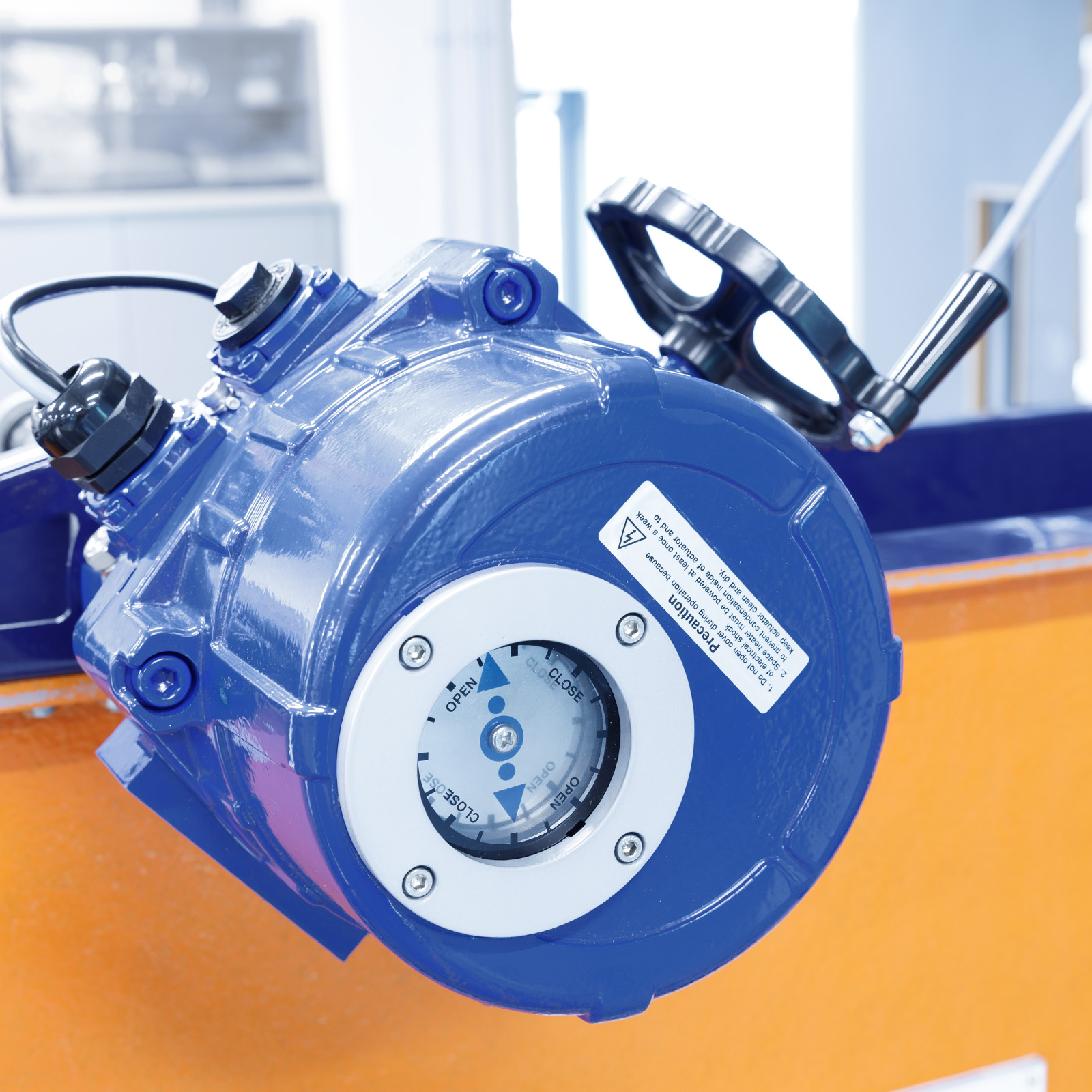
The Armfield tilting flume is fitted with a precision mechanical jacking system interlinked through a series of support jacking stations the jacking system can be either manually operated by a hand-wheel or motor driven and incorporated into the control system.
S6-35: Wave Generator
The S6-35 wave generator has a variable speed drive motor and is used to obtain regular waves.
- Simple, regular, flap-type generator designed to be mounted on the flume discharge tank.
- The wave generator is used to propagate waves in the working section
Note: Essential accessory S6-36 Beach

S6-40: Instrument Carrier
- Position lock
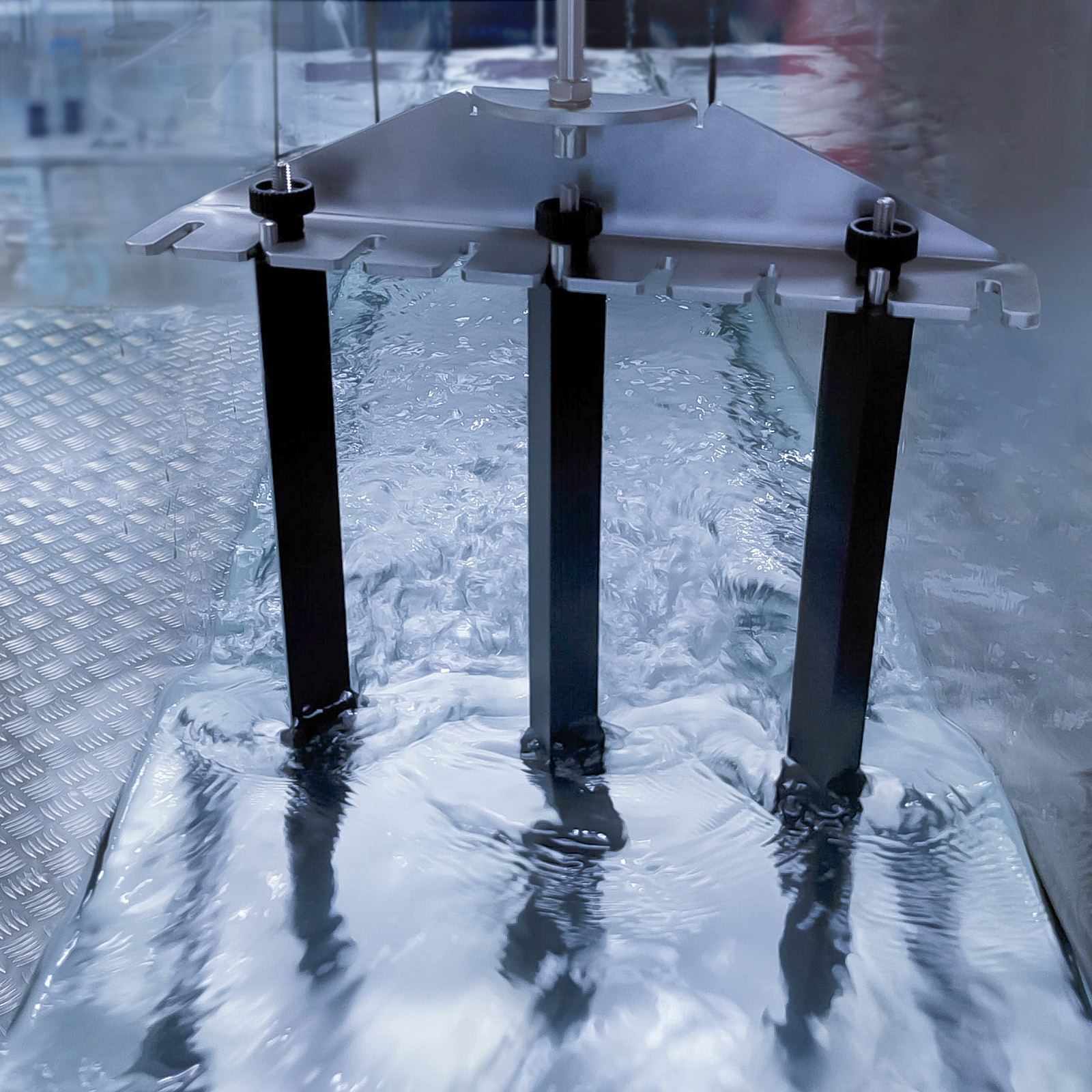
- The instrument carrier is a carriage with 3 point suspension that uses the instrument rails along the top of the flow channel to provide both longitudinal and transverse movement
- Different instruments can be attached to the carrier using appropriate holes in the triangular plate

S6-45: Random Wave Maker
The S6-45 utilises the base hinge weir in the discharge tank of S6-MKIII Flume as the paddle to propagate random or regular waves in the working section
The form of waves is created using computer software via a PC that is connected to the wave maker
Note: PC not supplied

Flume Models – S6-MkIII Standard flume
Non-corroding materials have been used to reduce maintenance time and increase the working life of the models.
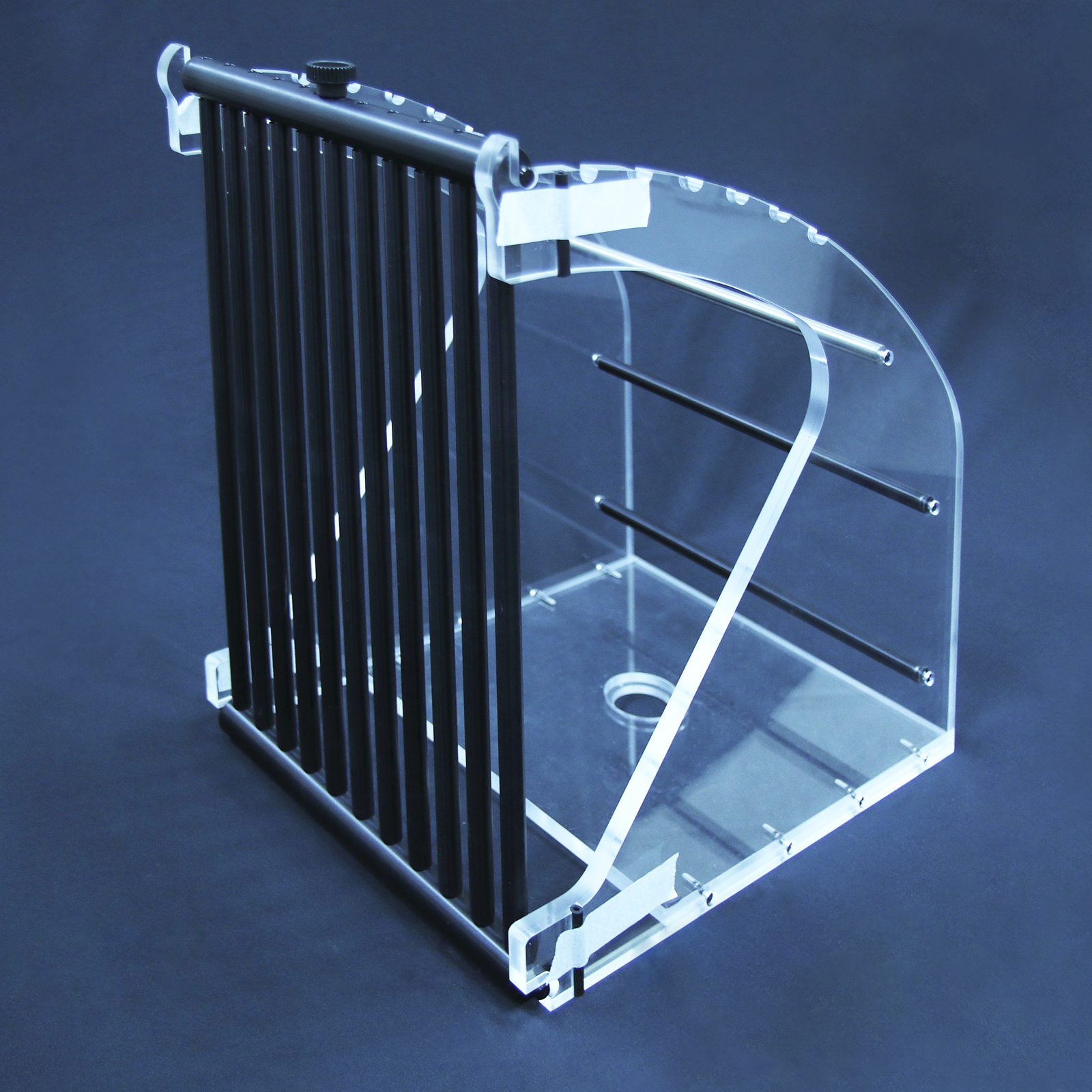
S6-20 Plate Weirs (Stainless Steel)
- A screw operated adjustable undershot plate weir (Full width)
- A mounting frame with vent pipes (to aerate the nappe) to accommodate the following interchangeable overshot thin plate weirs:
-
- Rectangular Notch (Full width)
- Rectangular Notch (100 mm wide)
- 90° ‘V’ Notch.
- 60° ‘V’ Notch.
- Trapezoidal (Cipolletti) Notch (Rectangular with ‘V’ ends).
- Sutro Notch (Profiled to give linear height change with flow).
Note: End user fabrication and use of own weirs are possible and encouraged for project work.

S6-21: Broad Crested Weir consisting of:
- A rectangular streamlined weir moulded from GRP.
- A rectangular sharp cornered weir moulded from GRP (can be used in isolation or in combination with streamlined weir to increase its height).

S6-23: Ogee Weir & Manometer Board
Eight pressure tapping’s (2 upstream, 5 downstream, 1 at apex) complete with multi-tube piezometer board.
- Determine pressure variations at the surface of the Ogee Weir at different flow conditions and observe the flow patterns obtained
- Determine the relationship between flow-rate and upstream head
- Calculate the discharge coefficient

S6-31: Crump Weir
Single pressure tapping at apex, complete with piezometer tube.
- Determine the relationship between upstream head and flow-rate
- Determine the modular limit and to observe the flow patterns obtained
- Determine the head at the apex of the weir and its relationship with flow-rate and depths upstream and downstream
- Reinforced Apex to avoid damage

S6-50: Culvert
The S6-50 is used to determine the head/discharge characteristics and to determine the conditions necessary for the Culvert to run full.

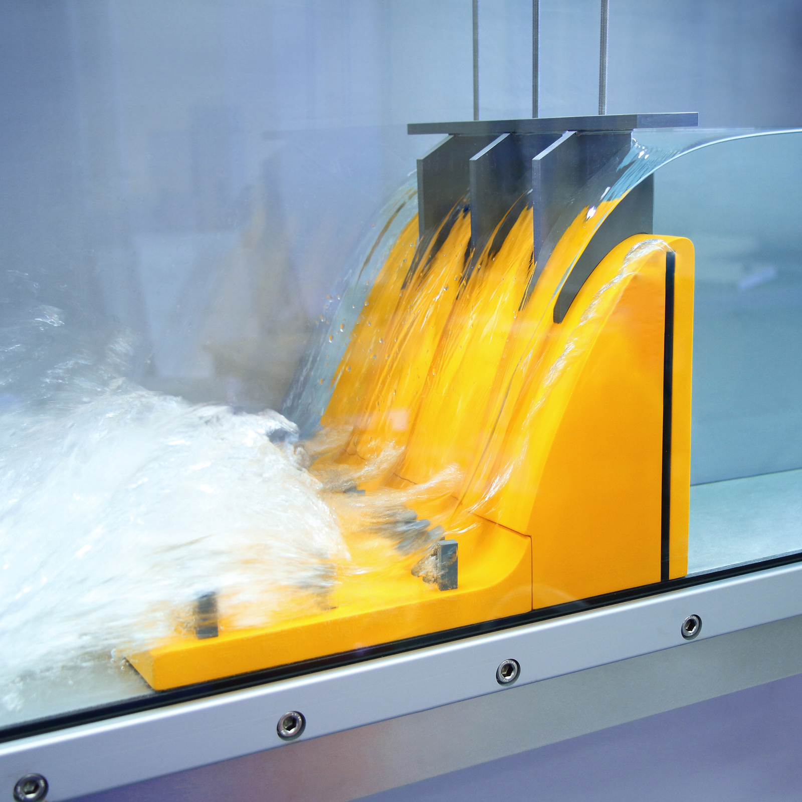
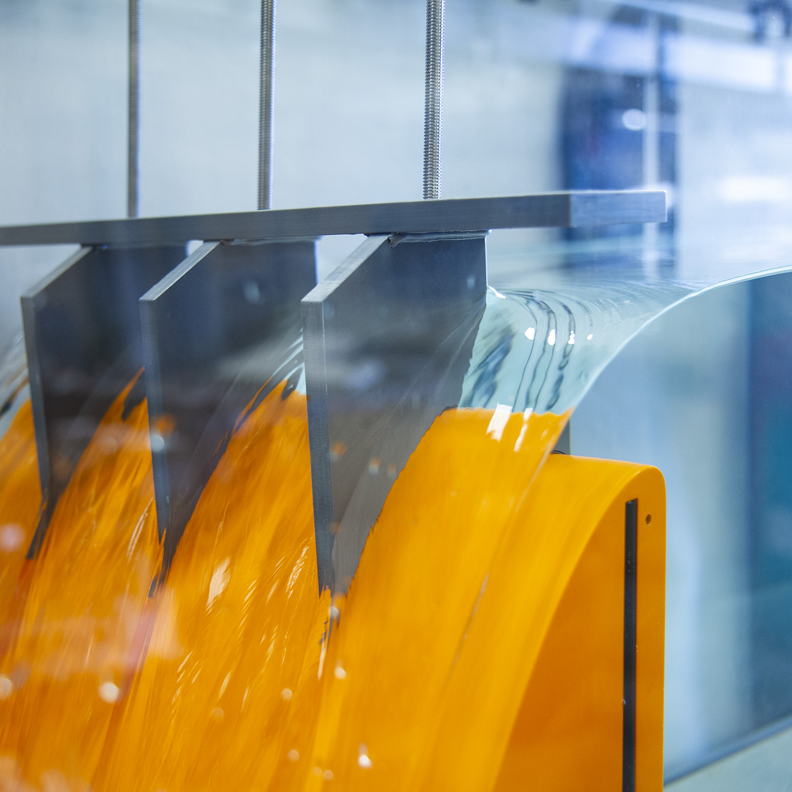
S6-24: Dam Spillway Models
To observe flow patterns associated with the flow of water over a Dam Spillway. Complete with the following interchangeable downstream sections:
- Spillway toe
- Roller bucket toe
- Apron with removable energy dissipater
- Gravel Box and Stop Logs

S6-25: Syphon Spillway
Complete with adjustable air regulation.
- Determine the relationship between upstream head and flow-rate through a siphon spillway in the ‘Blackwater’ fully primed condition.
- Calculate the discharge coefficient
- Observe the operation of the siphon as it primes and de-primes

S6-26: Self-regulation Syphon
- Determine the relationship between upstream head and flow-rate through a self-regulating (air regulated) siphon
- Calculate the discharge coefficient
- Observe the operation of the siphon as it primes and de-primes

S6-27: Roughened Beds
- Gravel Bed – Loose gravel bonded to a moulded GRP support to line the bed of the flume. Two different sizes of gravel are supplied with a different roughness factor. Each set consists of three modules arranged to cover a 2.5 m long section of flume.
- Corrugated Bed
Each 2.5m long bed consists of three sections
To investigate the effect of a roughened or corrugated bed on the depth of water at different flow rates
Obtain appropriate coefficients to satisfy the Manning Formula

S6-28: Vibrating Pile
For the study of vortex shedding by piles and tall structures.
- Investigate the effect of flow rate and Reynold’s number on the flow patterns around a vertical pipe
- To investigate the effects of resonance on the pile

S6-29: Lift & Drag Balance with Models
Three models – large and small diameter cylinders and an aerofoil section.
- Determine and compare the drag force on two cylinders with different diameters at different water velocities
- Compare the drag force on a symmetrical hydrofoil and a cylinder with the same frontal area
- Determine the lift and drag forces produced by a symmetrical hydrofoil at different angles of attack and different water velocities

S6-22: Venturi Flume
A set of GRP mouldings for installation in the channel section to form a venturi flume.
- Determine the relationship between upstream head and flow-rate for water flowing through a venturi flume
- Calculate discharge coefficient and observe the flow patten obtained

S6-32: Parshall Flume
One of the most widely used methods of measuring the flow of water in open channels.
- Investigate the flow of fluid through a Parshall flume and compare the experimental measurements with standard reference graphs

S6-33: WSC Flume
Developed by Washington State College (WSC), this trapezoidal flume conforms more closely to natural channel sections and passes sediment even more freely than the Parshall Flume.
- Investigate the flow of fluid through a WSC flume and compare the experimental measurements with standard reference graphs
- Investigate the effect of submergence on the accuracy of measurements using a WSC Flume when the flume becomes drowned

S6-36: Beach
Wave absorption beach for use with S6-35 or S6-45 to reduce the effect of reflected waves.

S6-49: Sill
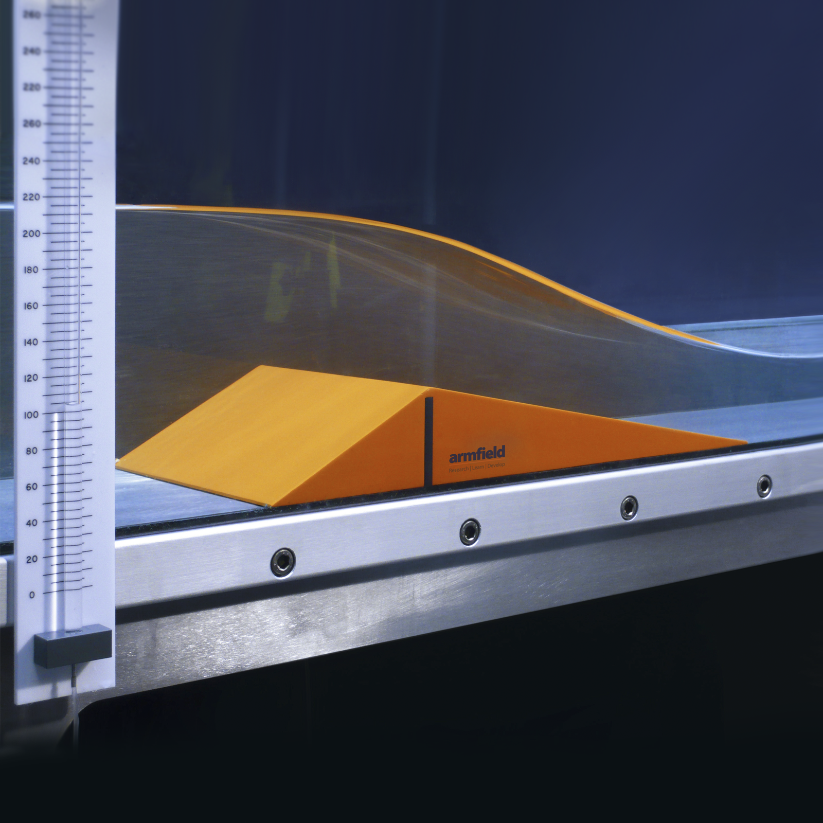
- The S6-49 is used to observe the flow patterns associated with the flow of water over different bed profile
- It allows the behaviour of open channel flow at a reduction of flow cross-section to be investigated

S6-47: Set of Piers
Investigate the backwater rise upstream of piers for both subcritical and supercritical flow around and between the piers and the effect of:
- Geometric shape of the pier
- High/low values of Froude number (Super/sub critical flow)
- Opening Ratio
- Multiple piers in combination
- Erosion/Scour caused by piers in sediment (option S6-MKIII-SL required)
- Angle of attack when piers are not parallel with the flow

S6-46: Radial Gate
- The S6-46 allows the relationship between upstream head and flow-rate beneath a radial gate under different operating conditions to be determined
- Discharge coefficient in each condition to be calculated

S6-48: Trash Rack
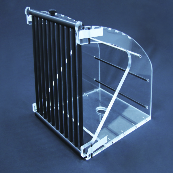
The S6-48 is used to determine the head-loss associated with trash rack design with regards to geometry of the rack spacing and the bar shape.
These are designed to filter floating & submerged debris and aquatic life from waterways that may otherwise damage downstream structures for example hydroelectric equipment.
S6-42 Velocity Meter & Mountings
- High speed probe supplied
- Velocity probe and digital meter, complete with mounting bracket suitable for attachment to the S6-40
- Orientation and height of the probe can be varied
- Range 0.6. to 3m/sec.

S6-30: Pitot Tube & Manometer Board
Complete with traversing carriage and vernier height adjustment, and an inverted paraffin water manometer for magnification of small pressure differences
Note: Requires S6-40 Instrument Carrier

S6-37: Zagni Flow Monitoring Systems
- Manual Monitoring System
- Consists of a free standing manometer board and instrument carriage fitted with Pitot tube and interconnecting tubing.
- This system may be used to establish the basic parameters of fluid flow in the channel including:
Invert slope
Surface profiles
Pressure profiles
Velocity profiles

There are numerous design features associated with Armfield flumes
* Not all features are appropriate for every channel.
- Accurate for education and research
- Extremely stable design, no user adjustments required to the flume bed
- Floor space requirements reduced to a minimum
- Fabricated high precision stainless steel channel bed
- Quick conversion to closed-loop recirculation for sediment transport studies
- Precision screw jacks provide accurate slope adjustment with minimum effort (powered jacks available as an option)
- Adjustable instrument rails with positioning scales fitted over the whole working length
- Fully profiled inlet tank fitted with stilling and smoothing devices
- Discharge tank with adjustable overshot weir and draft tube to avoid splashing and enhance noise reduction
- Modular construction supplied in pre-glazed sections for rapid and easy assembly on site
- Wave generation options, both regular and random
- Comprehensive range of optional accessories, instruments and models available
- Non-corroding durable GRP tanks throughout
- Transparent sides are of toughened glass, which is extremely strong, abrasion resistant, dimensionally stable, does not discolour or scratch and is inherently safe
- Working section allows adjust-ability, enabling extremely accurate setting
- Under frame designed to reduce load deflections to a minimum
- Close tolerances specified and achieved
Electrical supply: 3Ph, 50-60Hz
- Cold Water
Packed and crated shipping specifications
Volume & Gross Weight to be confirmed at time of order
Tilting configurable modular flumes S6-MKIII
Working section dimensions
Type: Tilting or standard flume
Length (in 2.5m modular increments): 5m
Width: 0.3m
Height: 0.45m
Above lists standard size flume, available in free discharge or recirculation.
Bespoke lengths and widths can also be offered.
Tilt parameters
Working Section 5M 7.5M 10M 12.5m 15m 17.5m
(+)% 5 5 4.5 3.6 2.9 2.5
(-)% 2.1 1.4 0.9 0.7 0.5 0.5
Total 7.1 6.4 5.4 4.3 3.4 3
- S6 MKIII flumes – cross section 300mm wide x 450mm deep
- S6-MKIII-5M-C Self Contained 5mtr Flume 415V/3Ph/50Hz*
- S6-MKIII-5M-D Self Contained 5 mtr Flume 208V/3Ph/60Hz*
- S6-MKIII-7.5M-C Self Contained 7.5mtr Flume 415V/3Ph/50Hz*
- S6-MKIII-7.5M-D Self Contained 7.5 mtr Flume 208V/3Ph/60Hz*
- S6-MKIII-10M-C Self Contained 10 mtr Flume 415V/3Ph/50Hz*
- S6-MKIII-10M-D Self Contained 10 mtr Flume 208V/3Ph/60Hz*
- S6-MKIII-12.5M-C Self Contained 12.5mtr Flume 415V/3Ph/50Hz*
- S6-MKIII-12.5M-D Self Contained 12.5 mtr Flume 208V/3Ph/60Hz*
- S6-MKIII-15M-C Self Contained 15 mtr Flume 415V/3Ph/50Hz*
- S6-MKIII-15M-D Self Contained 15 mtr Flume 208V/3Ph/60Hz*
- S6-MKIII-17.5M-C Self Contained 17.5mtr Flume 415V/3Ph/50Hz*
- S6-MKIII-17.5M-D Self Contained 17.5 mtr Flume 208V/3Ph/60Hz*
- S6-MKIII-SL Sediment Loop for S6-MKIII flume all lengths
- S6-MKIII-PJ Power Jacks for S6-MKIII flume all lengths
* includes Manual Jacks , Control Console with Pump and storage tanks -
S6-MKIII-PMP 16 Channel electronic manometer
-
S6-MKIII-WW Walkway
-
S6-MKIII-WB Window base
-
S6-MKIII-ADC Automatic depth control


