


S16 – Hydraulic Flow Demonstrator
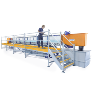
The Armfield S16 Hydraulic Flow Demonstrator is a free-standing accessory to the Armfield Hydraulic Bench which enables hydraulic phenomena associated with the flow of water through both open channels and closed conduits to be set up quickly, easily and visually demonstrated.
Description
The Armfield S16 Hydraulic Flow Demonstrator is a free-standing accessory to the Armfield Hydraulic Bench which enables hydraulic phenomena associated with the flow of water through both open channels and closed conduits to be set up quickly, easily and visually demonstrated.
Measurements taken in each configuration permit the associated flow conditions to be analysed.
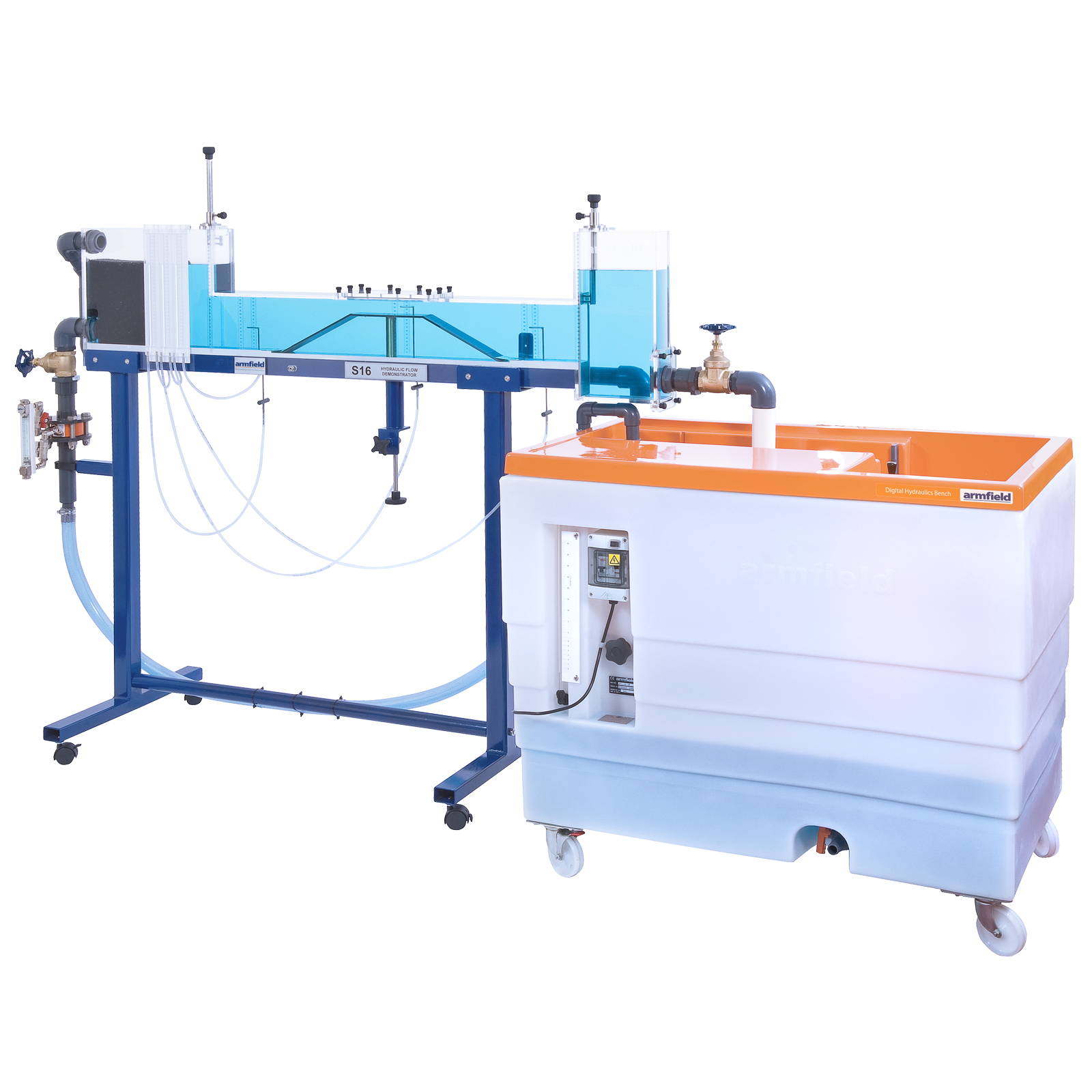
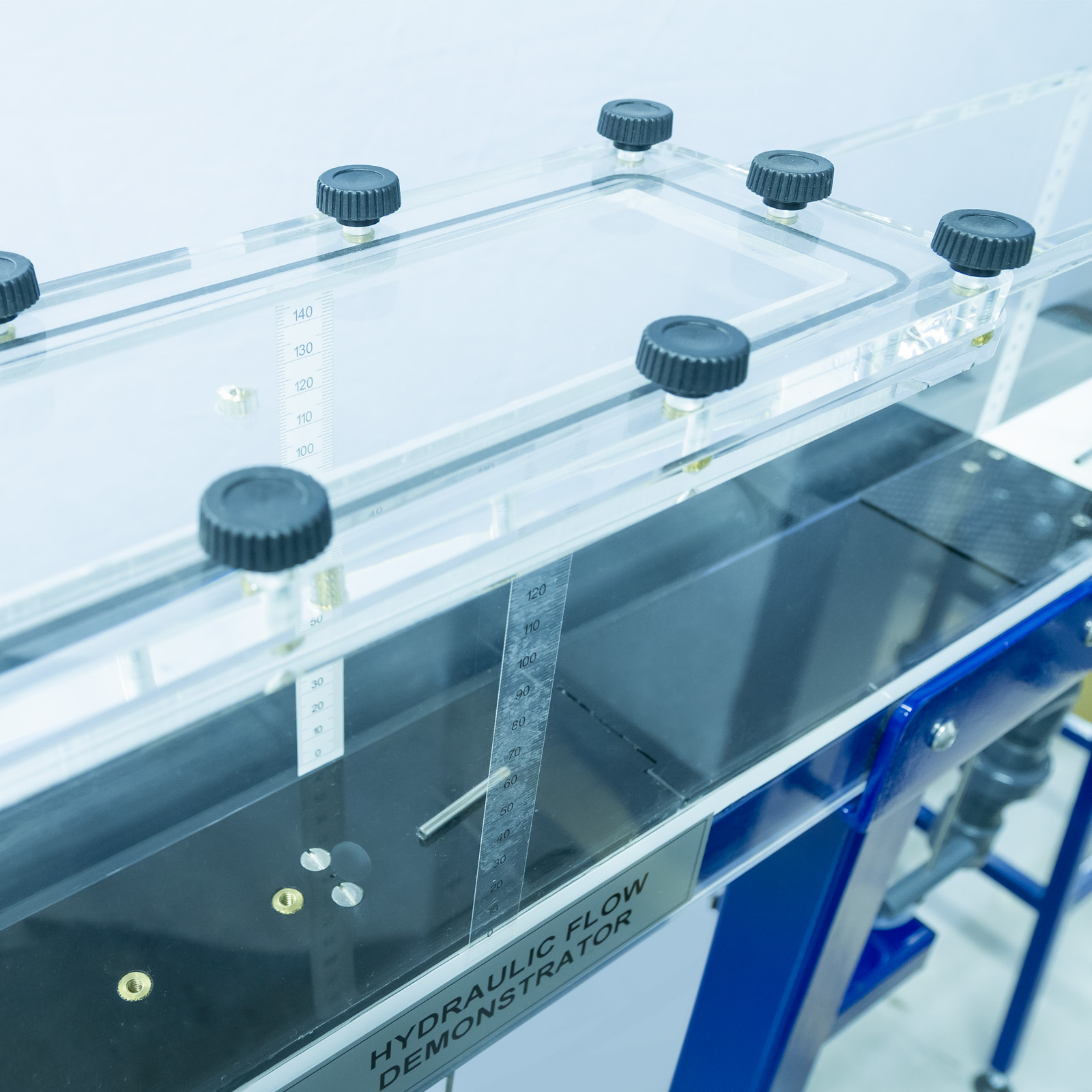
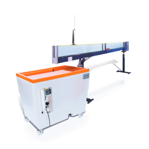
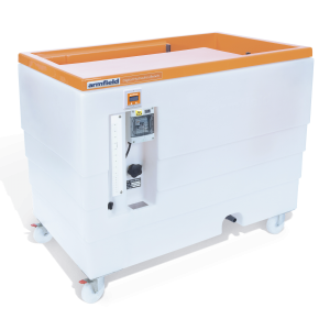
The flow channel of the S16 Hydraulic Flow Demonstrator is constructed using clear acrylic for visibility and is supported by a floor standing, metal frame fitted with castors for mobility.
The flow channel consists of an inlet tank with overflow and flow stilling arrangement, a rectangular working section and a discharge tank.
Control valves and adjustable weirs allow the flow conditions to be varied independently at the entry to and exit from the working section. The working section can be flooded to create a closed conduit or operate partially filled as an open channel.
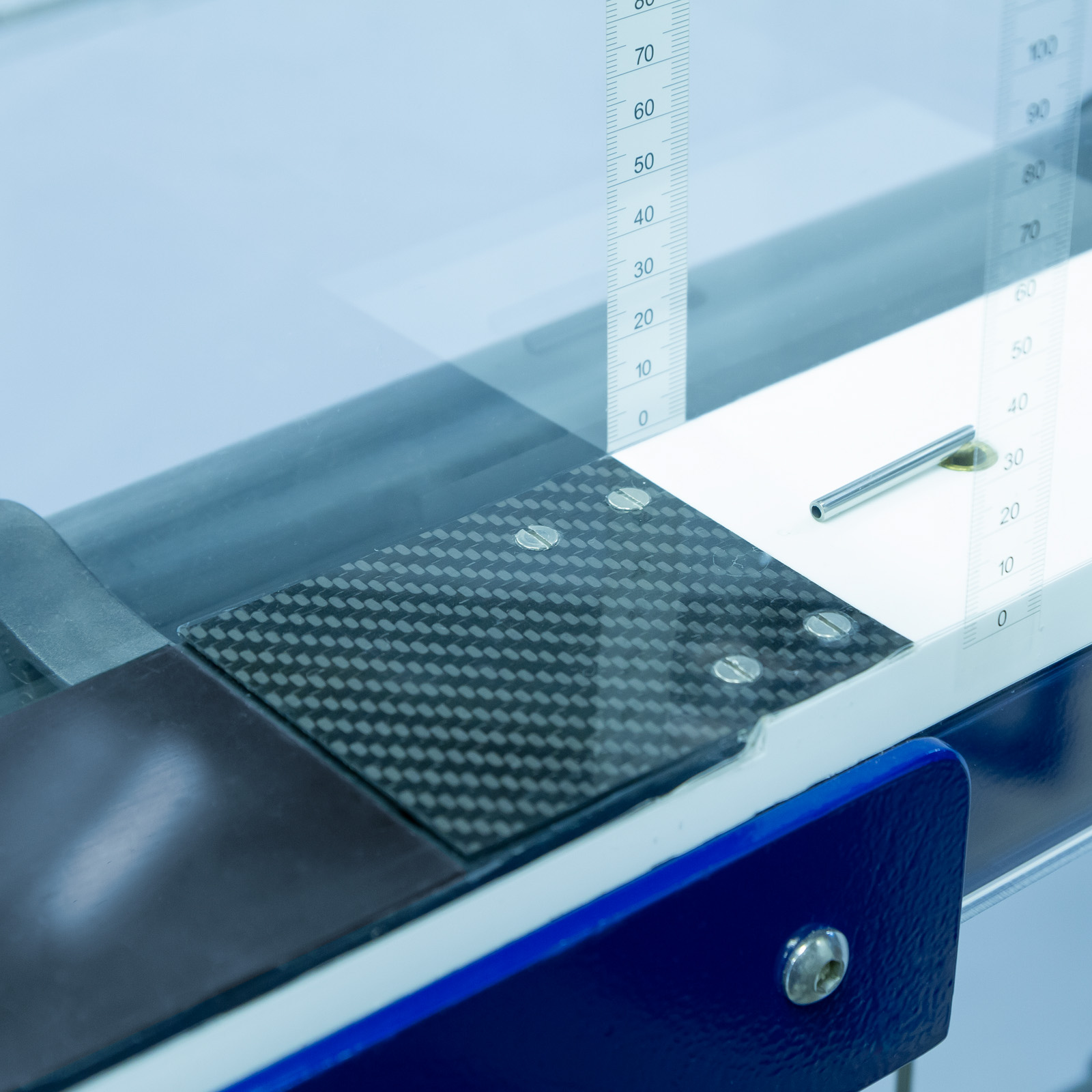
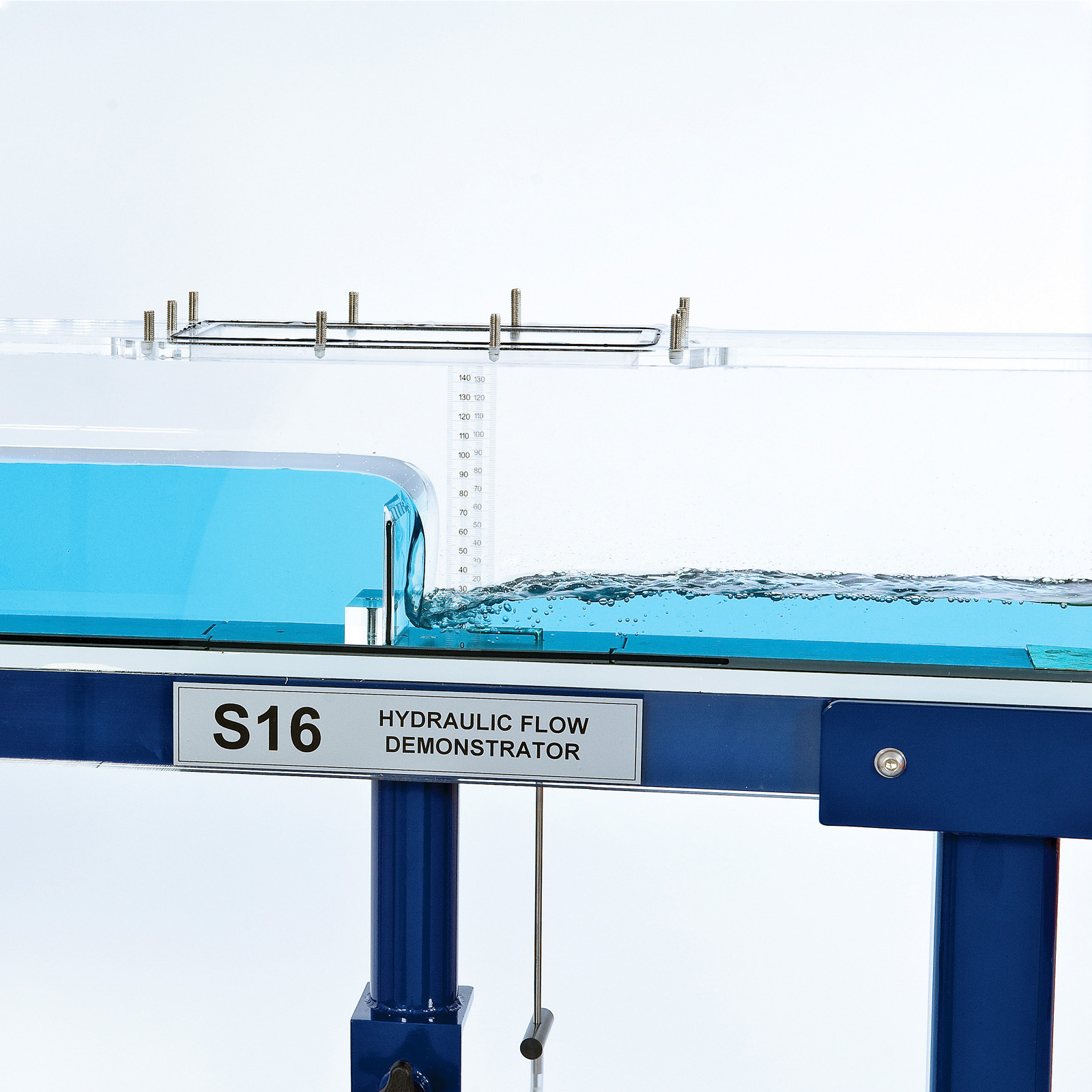
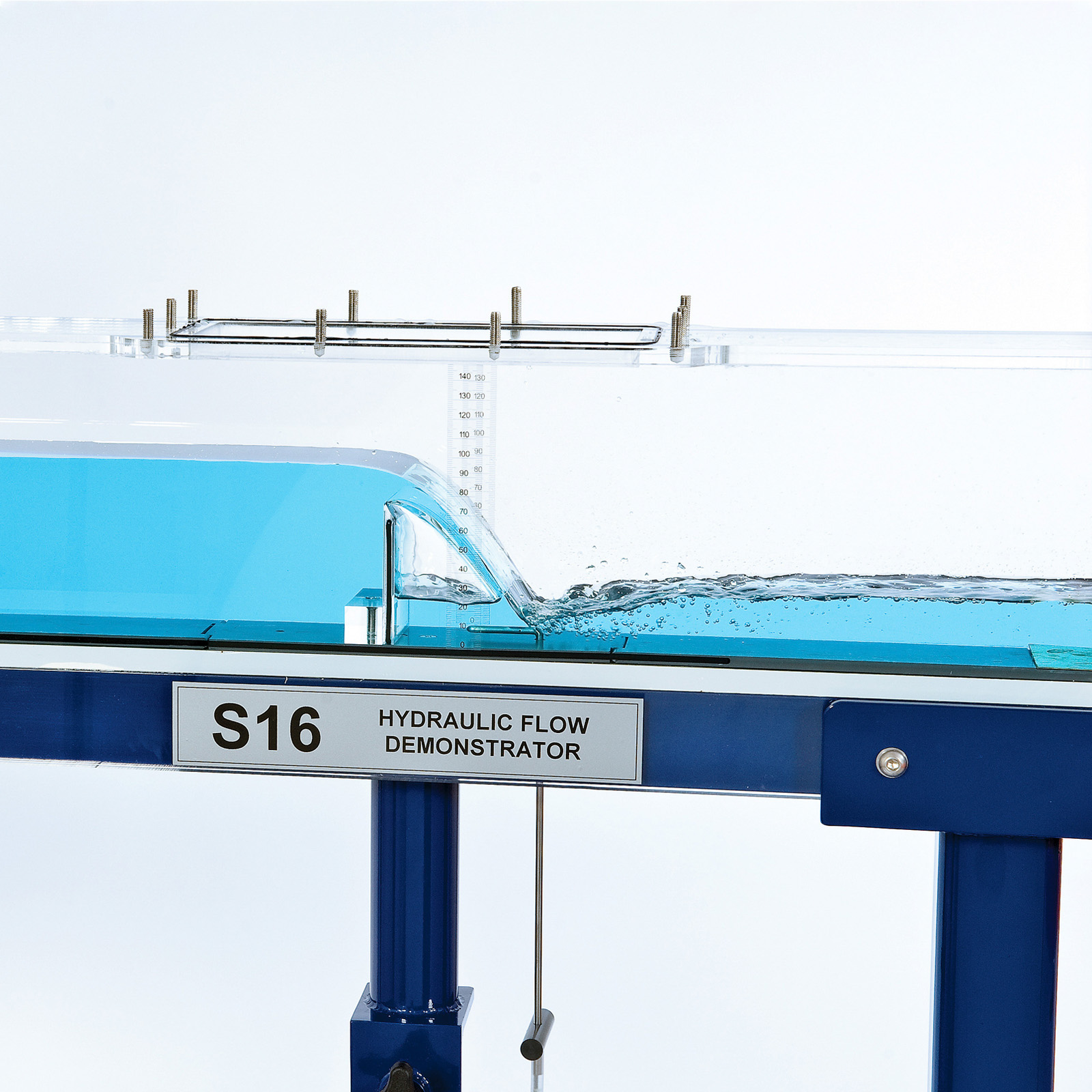
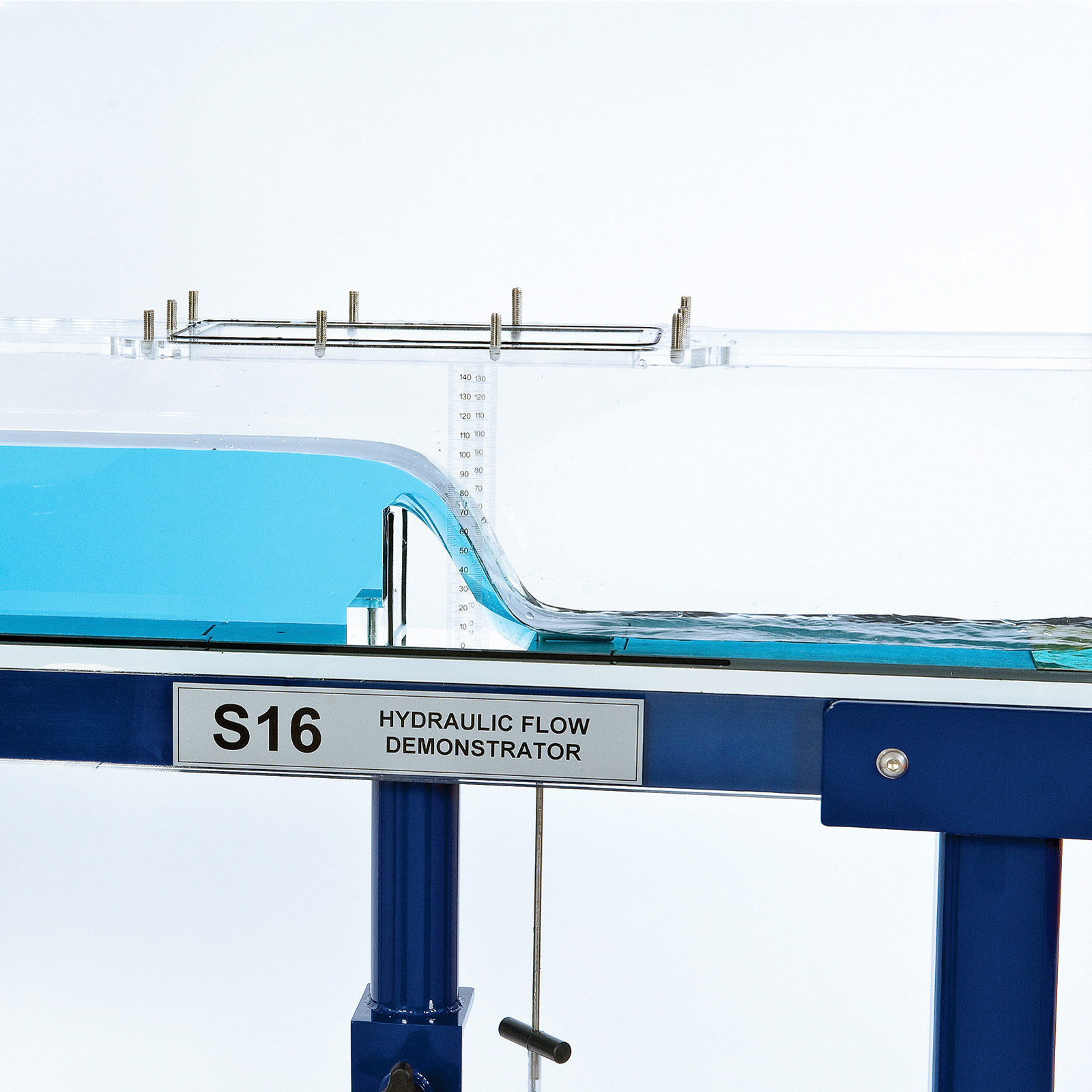
The most important feature of this equipment is the adjustable section of the bed which, together with its transition section (ramps), may be raised or lowered using an external actuator whilst the water is still flowing. This facility affords a striking demonstration of the significance of channel critical depth. It is also used to vary the cross section for demonstration of the Bernoulli equation in closed conduit flow.
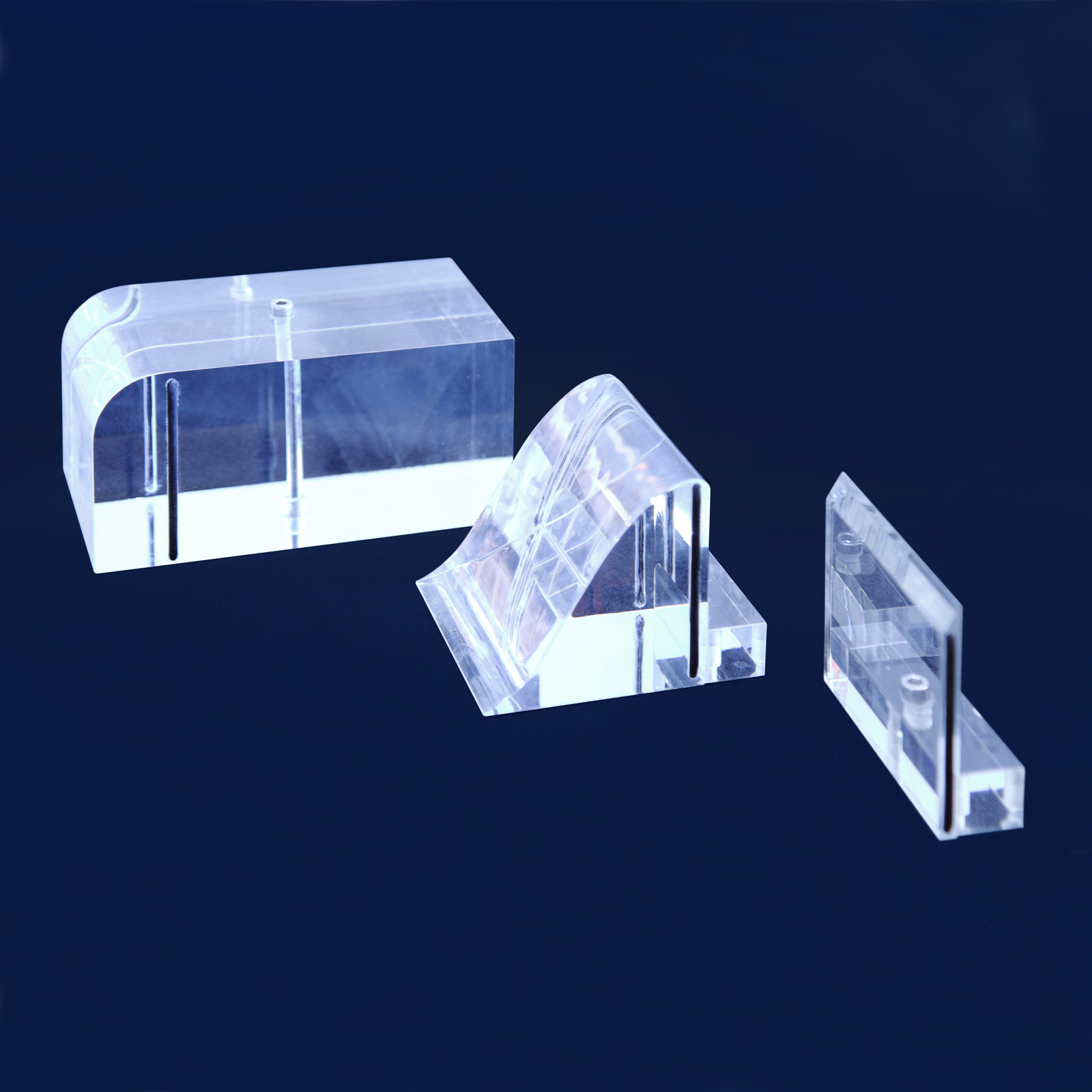
A removable panel in the roof of the working section allows models of typical hydraulic structures to be installed, namely; a sharp crested weir, broad crested weir (also used to create a culvert) and Ogee weir.
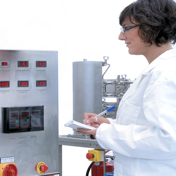
Pitot tubes and tappings connected to a multi-tube manometer allow total and static heads to be measured and compared at three locations in the working section. The height of the Pitot tubes is adjustable allowing the velocity profile to be determined at any position between the bed and the roof of the working section. Transparent scales allow all important heights and levels to be measured throughout the working section.
The S16 Hydraulic Flow Demonstrator is designed to be used in conjunction with an Armfield F1-10/F1-10-2 Hydraulics Bench, which provides a recirculating water supply and a volumetric measuring facility. The Flow Demonstrator can be used with an independent water supply of up to 1.6 litres/sec provided that water discharging from the channel can be intercepted.
.
Technical Specifications
Width of working section: 77mm
Depth of working section: 150mm
Length of working section: 1100mm
Maximum operating flow rate: 1.6 litres/sec
Features & Benefits
- Demonstrate flow through both open channels and close conduits using this highly visual accessory to the Hydraulics Bench
- Demonstrations can be set up quickly and easily, including varying the upstream and downstream flow conditions
- I deal for student project work – user constructed models of different hydraulic structures can be evaluated
- Unique elevating bed section and models of various hydraulic structures allow the difficult concepts of critical flow and energy changes to be clearly demonstrated and analysed
- Working section large enough for the various flow phenomena to be seen clearly by a group of students – enables a teacher to provide practical demonstrations at the same time as explaining the theory

The Armfield S16 Hydraulic Flow Demonstrator simply connects to a standard F1-10/F1-10-2 Hydraulics Bench to permit the study of the following basic aspects of fluid flow:
Open channel flow
- Flow beneath an undershot weir (sluice gate)
- Flow over sharp crested, broad crested and Ogee weirs
Using hydraulic structures to measure flow in an open channel
Effect of changes in upstream and downstream water level
Characteristics of clinging, aerated, depressed and drowned nappes
- Subcritical, critical and supercritical flow/depth
Changes in specific energy and control imposed by the minimum energy condition
- Characteristics of hydraulic jumps
Force and energy conditions in a hydraulic jump
Flow patterns associated with hydraulic jumps
Flow over drop structures/energy dissipation
- Changes in flow profile in relation to the Froude number (predicting flow conditions in an open channel)
- Observation of flow patterns associated with flow around hydraulic structures
- Velocity of gravity waves in shallow water/formation of surface waves near critical depth
- Project work – evaluation of user constructed hydraulic structures
Closed conduit flow
- Application of the Bernoulli and continuity equations to converging and diverging flow
- Effect of gradual and sudden changes in cross section (energy losses)
- Using a contraction as a flow measuring device
- Using a Pitot tube to measure velocity/velocity profile
- Flow through a culvert
- A floor standing flow channel for use with an F1-10/F1-10-2 Hydraulics Bench
- Working section 77mm wide, 150mm high and 1100mm long
- Can be configured to demonstrate flow in open channels and closed conduits
- Clear acrylic sides for good visibility of flow patterns created
- Stilling arrangement at inlet to promote smooth flow into the working section
- Section of bed can be elevated continuously and locked at the required height
- Discharge tank incorporates flow control valve for convenience in setting up
- Total and static heads indicated on multi-tube manometer connected to Pitot tubes and static tappings at three locations in working section
- Pitot tubes mounted through bed of channel for ease of priming and height adjustment (can be traversed from floor to roof to measure velocity profile)
- Transparent scales allow measurement of all important heights and levels
- Models of hydraulic structures supplied include undershot weir (sluice gate) at the inlet, overshot weir at the outlet, sharp crested weir, broad crested weir (also used to create a culvert) and Ogee weir
- Suitable for project work with alternative hydraulic structures (user created)
- Comprehensive instruction manual supplied
- Cold water
- Electrical supply (see F1-10 bench option)
PACKED AND CRATED SHIPPING SPECIFICATIONS
Volume: 3.4m³
Gross Weight: 250kg
Length: 2.20m
Width: 0.63m
Height: 1.60m
Weight (dry): 100Kg
- S16-10 Hydraulic Flow Demonstrator