


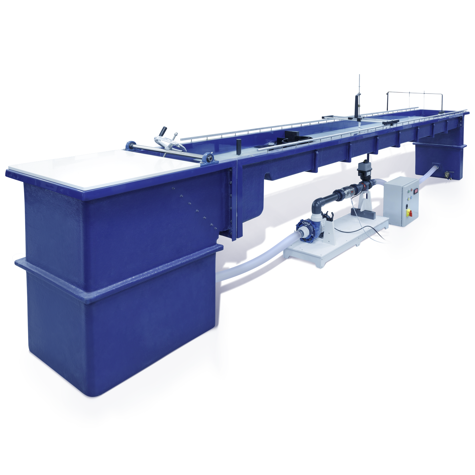
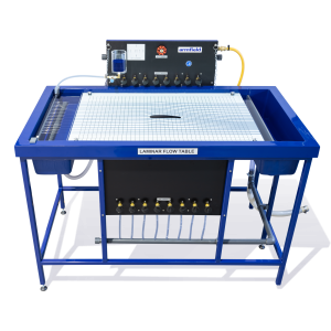
S2 – Mobile Bed and Flow Visualisation Tanks
The S2 – Mobile Bed and Flow Visualisation Tanks are used in two principal fields of study. The first involves detailed investigation of mobile bed situations. These may be in relation to watercourses or civil engineering structures.
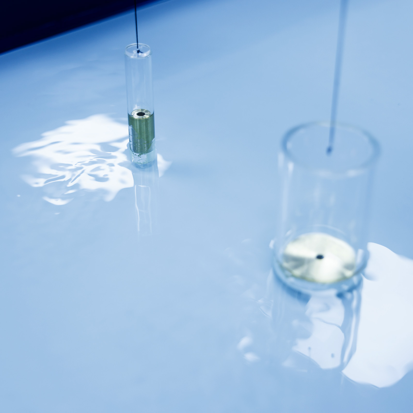
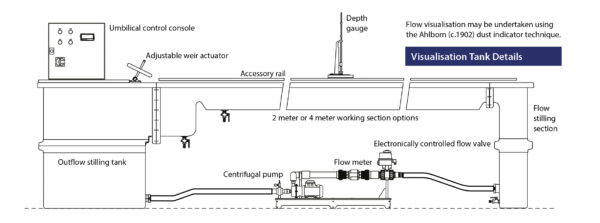
The second field involves two dimensional flow visualisation. This may be undertaken using the Ahlborn (c.1902) dust indicator technique or by any other suitable method of flow visualisation.
Description
Practical demonstration and visualisation are essential elements of fluid flow study.
The S2 – Mobile Bed and Flow Visualisation Tanks are used in two principal fields of study. The first involves detailed investigation of mobile bed situations. These may be in relation to watercourses or civil engineering structures.
The second field involves two dimensional flow visualisation. This may be undertaken using the Ahlborn (c.1902) dust indicator technique or by any other suitable method of flow visualisation.
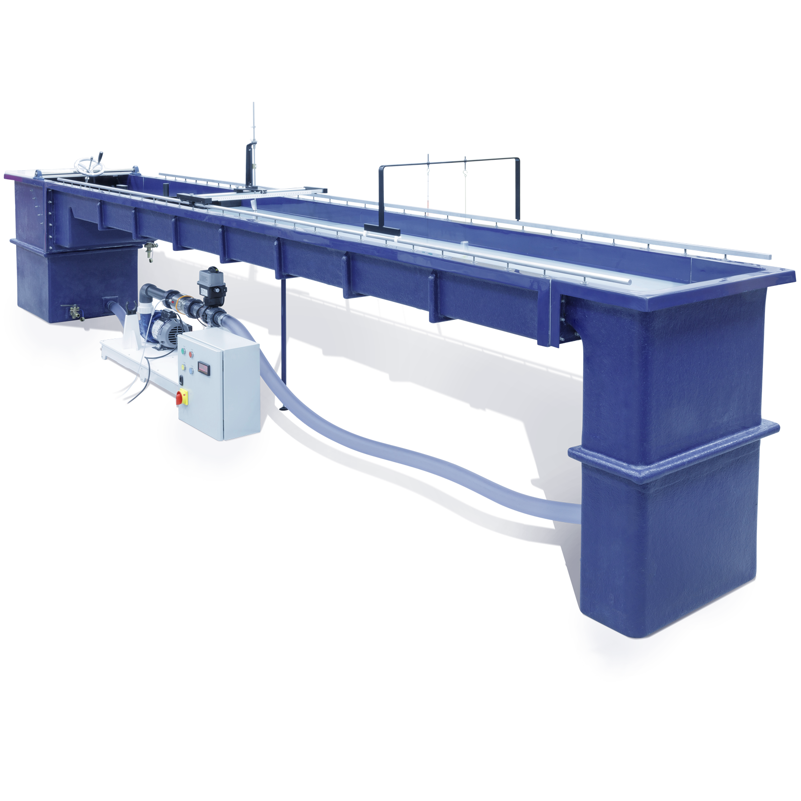
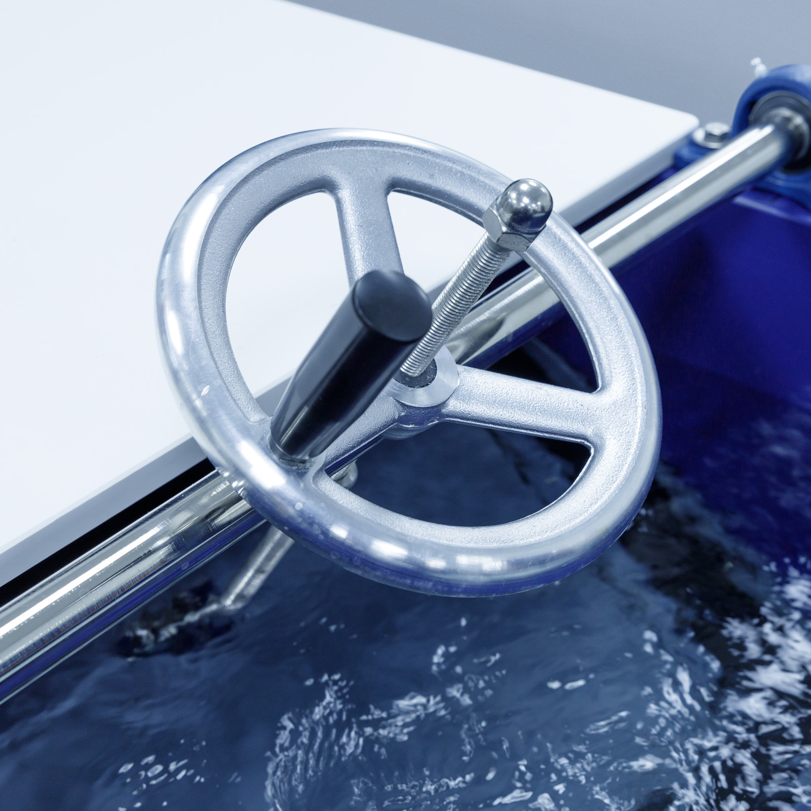
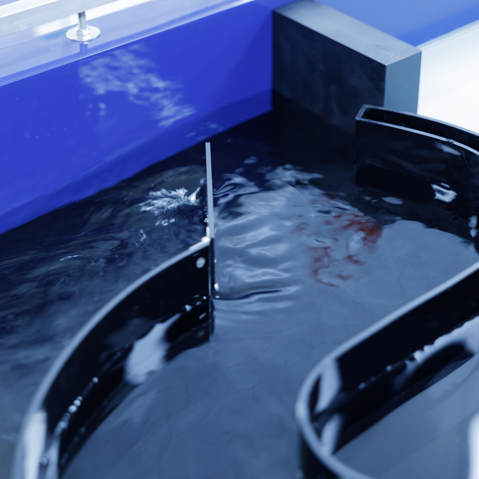
The tank is moulded from self coloured Oxford Blue (BS0105) glass fibre reinforced plastic with steel reinforcements to provide rigidity. It is manufactured in three sections; the inlet tank, the working section and the discharge reservoir tank. The sections are joined by flanged connections and despatched from the factory as a complete assembly. A drop-tight adjustable overshot weir with upstream sand trap is accommodated within the discharge tank. The inlet tank features a perforated baffle plate which spreads the flow evenly across the width of the table.
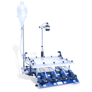
A removable glass sheet coloured blue on one side and white on the other, is provided to cover the sand bed when flow visualisation experiments are in progress. A pair of adjustable aluminium instrument rails are fitted to the top of the tank. These extend over the full length of the working section and one rail carries a positioning scale.
The depth gauge supplied is used to measure the water level and to map the contours of the sand bed produced during exercises.
It is provided with a stainless steel hook and point and incorporates a Vernier scale enabling levels to be determined accurately.
The gauge is designed for mounting on the instrument carrier assembly which can be positioned over any point of the working area. The main carrier (longitudinal traverse) is provided with a locking device and cursor to operate in conjunction with the instrument rail scale.
The sub-carriage (transverse traverse) operates on rails provided by the main carriage. There is again a transverse scale and locking device. The correct use of the apparatus is described in a comprehensive manual supplied with the tank.
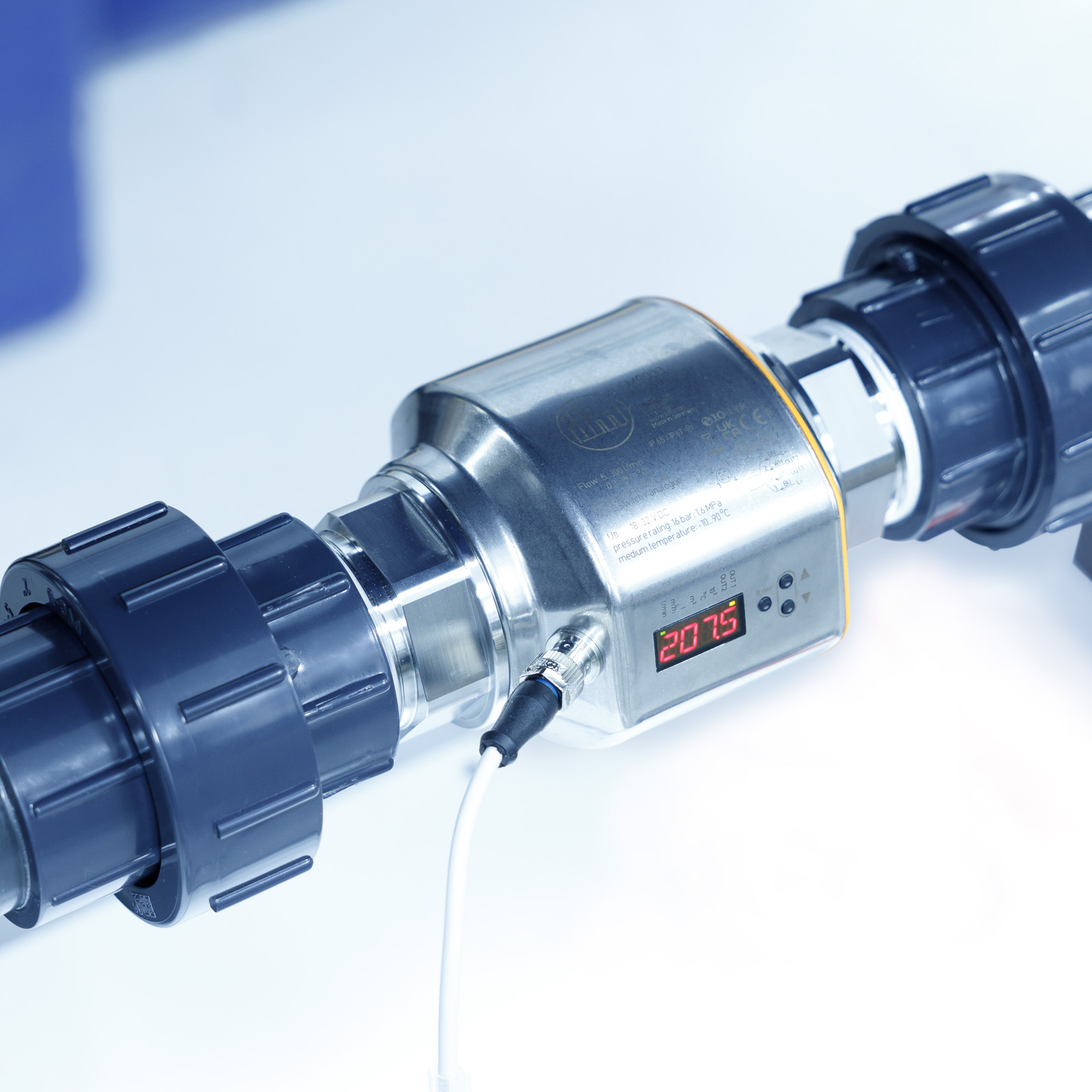
Water flow is provided by a centrifugal pump made of materials which are selected for their corrosion resistance as is the pipework which includes an electrically operated flow regulating valve.
A GRP moulding carries the pump, control valve, rigid pipework and ‘in-line’ flowmeter.
The assembly is connected to the tank by flexible hoses. The motor starter and digital meter readout are mounted in a table top cabinet supplied complete with the required flexible cables.
The tank is available with optional working lengths:
Model S2-2M: working length 2m
Model S2-4M: working length 4m
Technical Specifications
Working area: 2 m x 610mm or
4 m x 610mm
Max water depth: 120mm
Thickness of sand bed: 60mm
Flow range: 0-3.6 litres/sec
Sump capacity: 300 litres
Accuracy of flow metering: ±1.5% of full scale deflection
Features & Benefits
- Self-contained recirculating water tank: Ideal for flow visualization and mobile bed studies, providing a controlled and efficient learning environment.
- Durable construction: Made from glass-reinforced plastic with non-corroding materials, ensuring long-lasting use even in water-based experiments.
- Spacious working section: With dimensions of 2m (or 4m) x 610mm and a flow range of 0-3.5 liters/sec, it accommodates a wide variety of experiments.
- Versatile models and accessories: Comes with 15 models and accessories, plus a colored glass sheet for easy transition between mobile bed and flow visualization modes.
- Portable control console: Housed in a portable console with water-safe connectors and flexible cable, offering ease of use and setup for a vast array of experiments.
This setup provides flexibility, durability, and a comprehensive toolkit for fluid mechanics studies.

Mobile bed experiments
- Two-dimensional flow patterns by the Ahlborn technique
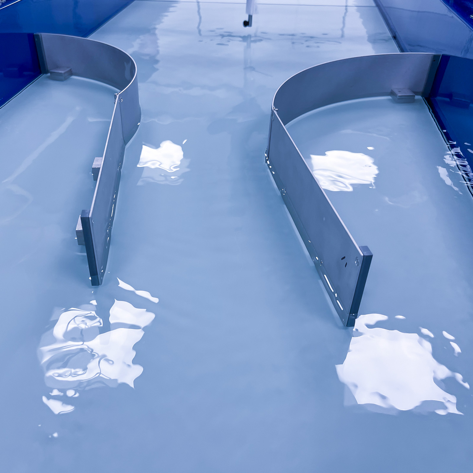
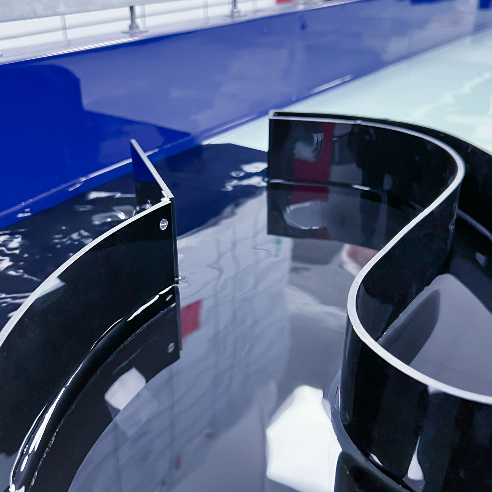
– Converging flow in a curved entry
– Diverging flow from a nozzle
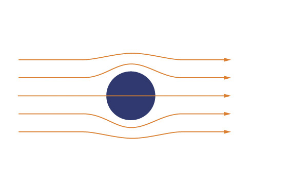
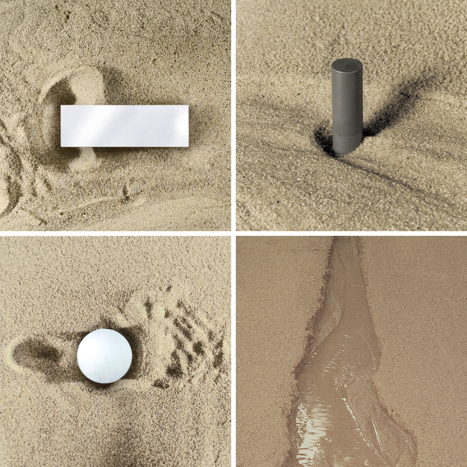
– Flow around isolated bodies
Circular cylinder
Rectangular block
Tee shapes
Symmetrical aerofoil parallel to the flow
Symmetrical aerofoil at incidence
Diamond shape with and without suction
– Arrays of cylinders
– Free jets
– A turbulent jet
– A laminar jet
– Confined zones of separated flow
– Flow past a gate-slot
– Elongated tee and step
– Simulation of a hydraulic jump
– Protection for a spillway toe
- Velocity distribution in duct flow
– Flow in a smooth-walled pipe
– Flow past a rough boundary
- Hydraulic analogy to compressible flow
- Three-dimensional flow patterns by the Ahlborn technique
– Influence of normal forces on boundary layer flows
Decelerating flow near a corner
Boundary layer flow in a curved path
– Simulations of practical three-dimensional flow patterns
Bridge piers and piles
Spurs (or groynes) and wall discontinuities
Tee junctions in irrigation systems
Meandering rivers
- Characteristics of meandering water courses
- Experimental investigation of erosion and deposition
- Boundary layer suction demonstration
- Boundary layer flows
- Experiments with loose boundaries
– Bed movement near a circular cylinder
– Alleviation of erosion around a cylinder
– Bed movement near non-circular bridge piers
– Bed movement near groynes and projections
– Ripple formation in fine sand
- Hydraulic model studies in an Ahlborn tank
– Operation of a gated weir
– Cause of damage to an irrigation drop structure
– Curved flow in a channel with a bend
– Forces on moored ships
– Circulation in a lock
- Unsteady flow patterns
– Unsteady boundary layer growth of a cylinder
– Eddy generation of an oscillating point of separation
Flow patterns near a separation point
– Unsteady flows near stationary boundaries
Eddy shedding from a cylinder
Excitation of lateral standing waves in a flow channel
– Flow-induced vibration of boundaries
Vibration of cylinders
Lateral vibration of a box


- A self contained recirculating water tank for flow visualisation and mobile bed studies
- The tank is manufactured from glass reinforced plastic and all components in contact with water are of non-corroding materials
- The working section has minimum dimensions of 2m (4m) x 610mm and the flow range is 0-3.5 litres/sec
- Fifteen models and accessories are included as standard and a sheet of coloured glass allows rapid changeover from mobile bed to flow visualisation mode
- All controls are housed in a portable console which includes a flexible cable and water safe connectors
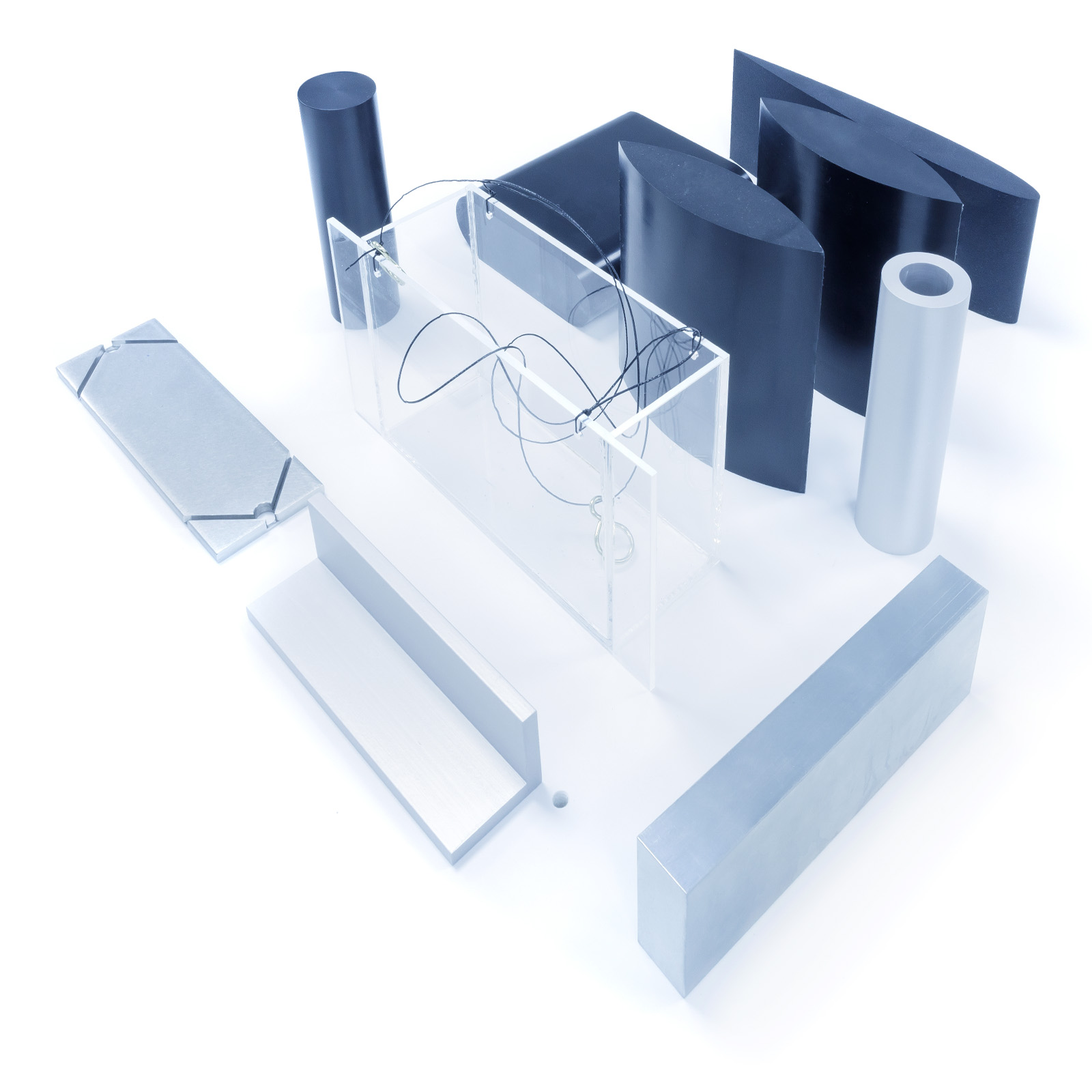
A wide range of models and accessories is supplied as standard with the Mobile Bed and Flow Visualisation Tank
- Hook and point gauge
- Plasticine
- Water soluble paint (white & black)
- Hypodermic tube & flexible tube
- Rectangular bridge piers (x2)
- Cylindrical bridge piers (x2)
- Round end bridge piers (x2)
- Special bridge piers (x2)
- Aerofoil
- Gate grooves (x2)
- Angles (x6)
- Tees (x12)
- Cylinders
- Set of tank strips/baffles (2x 225mm, 2x 300mm, 2x 600mm, 2x 900mm)
- Side wall meanders (x2)
- Pendulum support frame
- Small pendulum
- Large pendulum
- Swing box
- 90° angle walls (x2)
- Clear acrylic cylinder (perspex)
- Irrotational bend
- Syphon tube
- Bellmouth entries (x2)
- Retaining block
- Swing box weight
- Cork floats (x5)
Electricity supply:
S2-2M-A: 220/240V/1ph/50Hz
S2-2M-B: 120V/1ph/60Hz
S2-4M-A: 220/240/1ph/50Hz
S2-4M-B: 120V/1ph/50Hz
Cold water
PACKED AND CRATED SHIPPING SPECIFICATIONS
S2-2M
Volume: 3.70m³
Gross Weight: 590kg
S2-4M
Volume: 5.70m³
Gross Weight: 750kg
S2-2M
Length: 3.70m
Width: 0.71m
Height: 2.0m
S2-4M
Length: 5.70m
Width: 0.71m
Height: 2.0m
- S2-2M-A
- S2-2M-B
- S2-4M-A
- S2-4M-B