


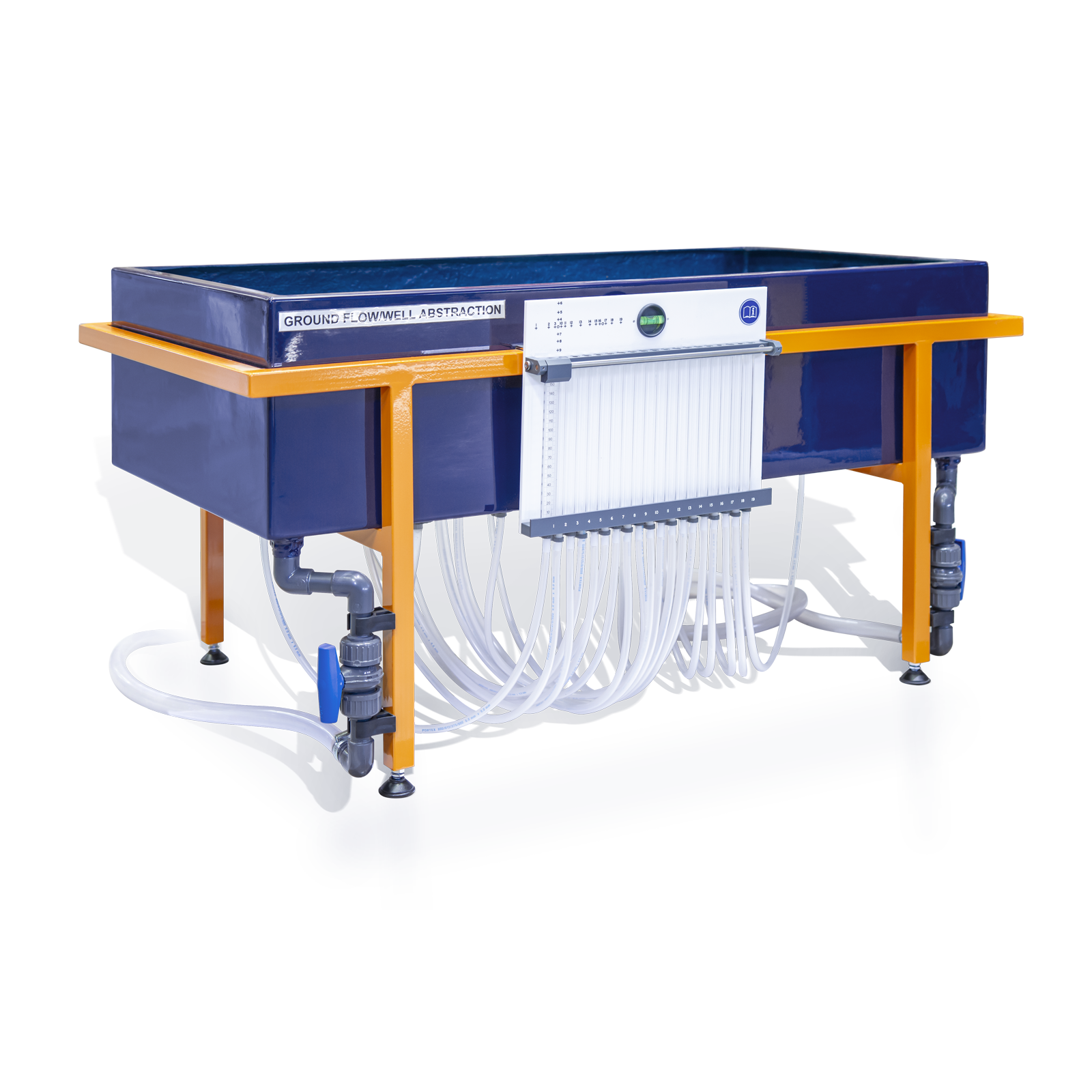


S11 – Ground Water Flow Unit
The S11 Ground Water Flow Unit is capable of demonstrating on a small scale, the hydrological principles of ground water flow and applications of these.
Description
The S11 Ground Water Flow Unit is a bench-mounting apparatus is capable of demonstrating, on a small scale, the hydrological principles of ground water flow and the applications of these to certain engineering constructions. The demonstrations are of interest to geologists and geographers concerned with subsurface water flows.
The equipment is valuable in any practical coursework related to water resource engineering. Demonstrations of flood risks associated with land drainage works, the use of wells for water abstraction, de-watering and the drainage of lakes and polders are all readily performed.
The Armfield Ground Water Flow Unit allows simple three dimensional flow situations to be set up quickly and measurements of piezometric levels taken at appropriate positions within the model.
In addition the appropriate instructional information and accessories are supplied, instructors and students of engineering hydrology may readily construct further model situations for study.
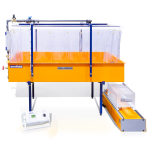
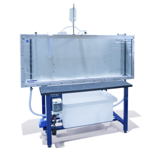
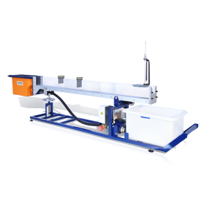
The sand tank is manufactured in glass re-inforced plastic for durability in service and is located in a painted mild steel frame which is designed for standing on a laboratory bench.
A diffused water inlet/outlet with associated flow control valve is installed at each end of the sand tank. This facility allows the desired water table to be established for the various demonstrations of groundwater flow.
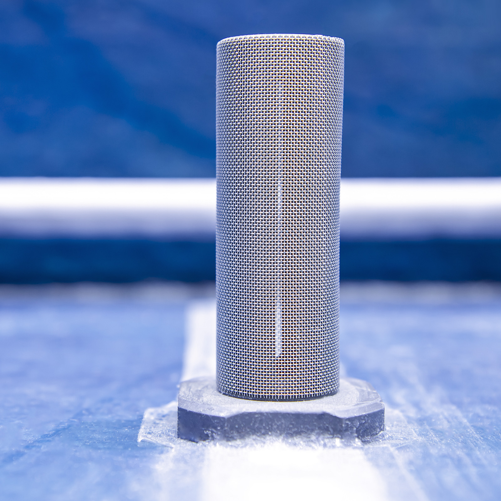
Two wells with control taps in the base of the tank allow studies of abstraction.
Nineteen tappings in the base of the tank arranged in a cruciform configuration are connected to a multi-tube piezometer on the side of the tank. These indicate the profile of the water table in the sand.
A sliding cursor permits measurement of any level.
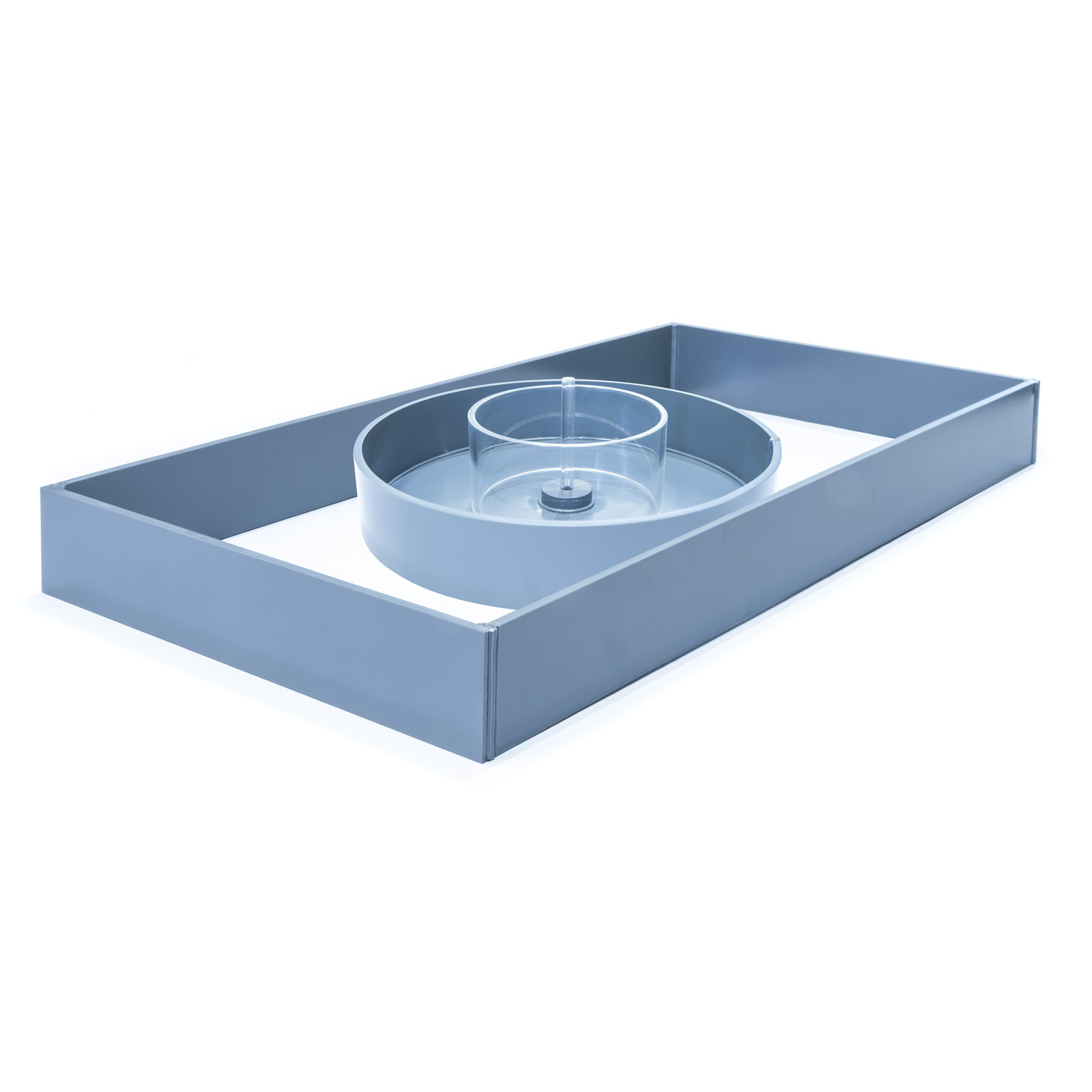
Appropriately sized cylindrical rings are provided as accessories for certain demonstrations described above.
Technical Specifications
Tank
Length: 0.999m
Width: 0.490m
Depth: 0.235M
Piezometer
Range: 0 to 155mm
Calibrated: 1mm intervals
Hydraulic gradient (Darcy’s law) resulting from groundwater flow between two potentials can be demonstrated visually. Levels in the piezometer tubes are plotted to show a linear profile (fig.1 opposite).
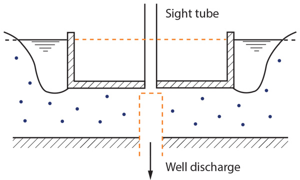
Water flowing into a well creates a depression in the water table. The contour of the water table is plotted using the levels in the Piezometer tubes.
Features & Benefits

- Demonstrate ground water flow and the resulting hydraulic gradients, including the effect of permeability
- Demonstrate cone of depression for a single well in an unconfined aquifer
- Demonstrate cone of depression for two wells in an unconfined aquifer
- Demonstrate the abstraction from a single well in a confined aquifer with radial symmetry
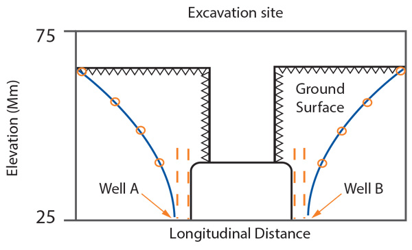
- Demonstrate the dewatering of an excavation site by locally lowering the water table using wells
- Demonstrate the draining of a man-made polder or natural lake and to investigate the factors involved

Results obtained can be compared with Depuit’s or Thiem’s formulae
Showing the construction of a single well in a confined aquifer with radial symmetry

A rectangular ring is used to form the sides of an excavation below the level of the water table. Wells are used to lower the water table in the vicinity of the excavation. Thus the excavation is prevented from filling with water.
A profile of the water table can be obtained when using two wells simultaneously. It is possible to compare the result with theoretical results obtained for a single well using the method of superposition.

A large rectangular ring is used to create a polder or lake. Water flowing into a ditch near the wall is drained via the two wells. The experiment differs from the dewatering of a site as drainage takes place from the floor of the polder.
- Hydraulics Bench (F1-10) or cold water supply
- Drain for cold water
- 0.1m3 of clean 0.6 – 2.0mm washed and graded coarse sand
PACKED AND CRATED SHIPPING SPECIFICATIONS
Volume: 0.8m³
Gross Weight: 100kg
Length: 1.115m
Width: 0.585m
Height: 0.530m
S11