


S1 – Drainage and Seepage Tank
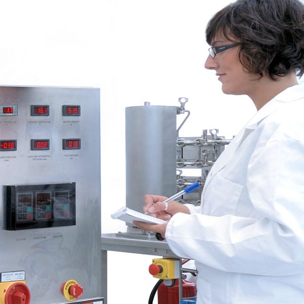
Practical demonstration and visualisation are essential elements of fluid flow study.
The S1 Drainage and Seepage Tank has been designed to allow students to make an experimental study of flow through permeable media.
Description
Practical demonstration and visualisation are essential elements of fluid flow study.
The S1 Drainage and Seepage Tank has been designed to allow students to make an experimental study of flow through permeable media.
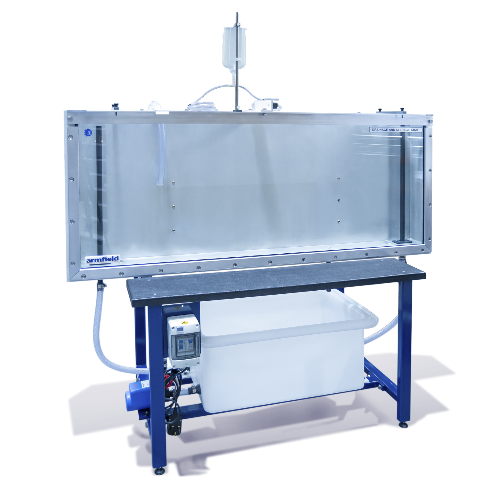
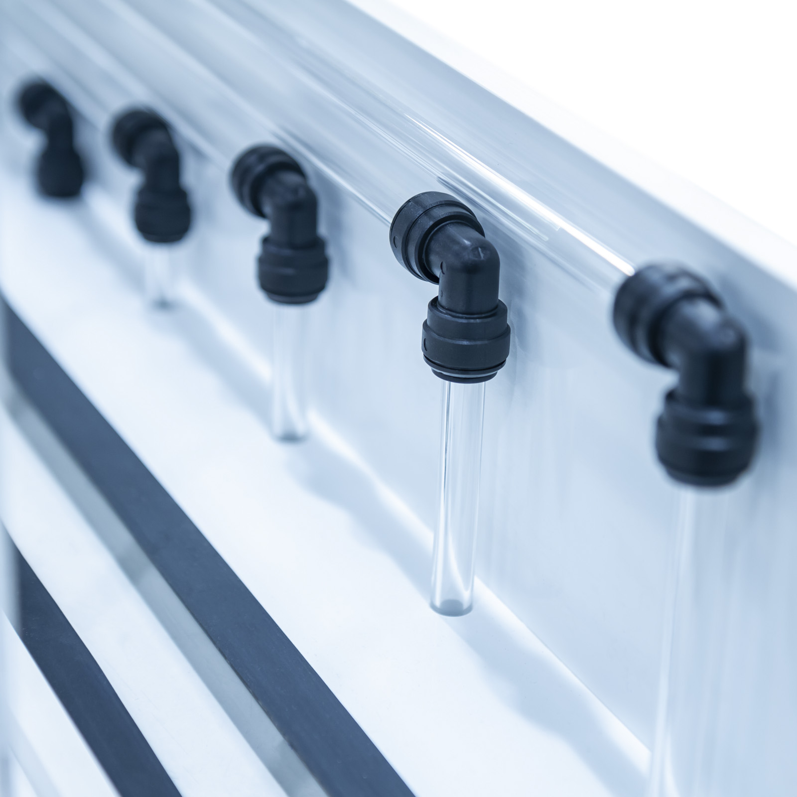
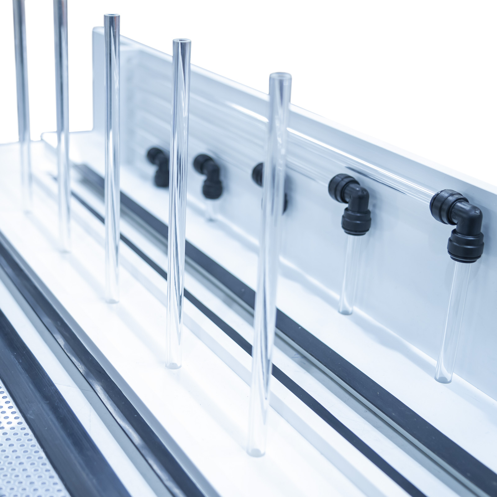
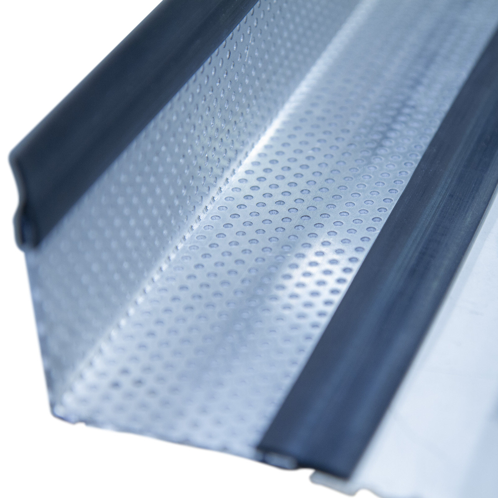
The bed of the tank is made from painted mild steel while the sides of the tank are supported and sealed by a well proven method which allows free access to the interior and results in minimum sight obstruction. One side is of toughened glass to give good scratch-free visibility over a long period of use while the other is made of aluminium which permits the insertion of pressure tapping points as required. The ends of the tank are made of steel plate.
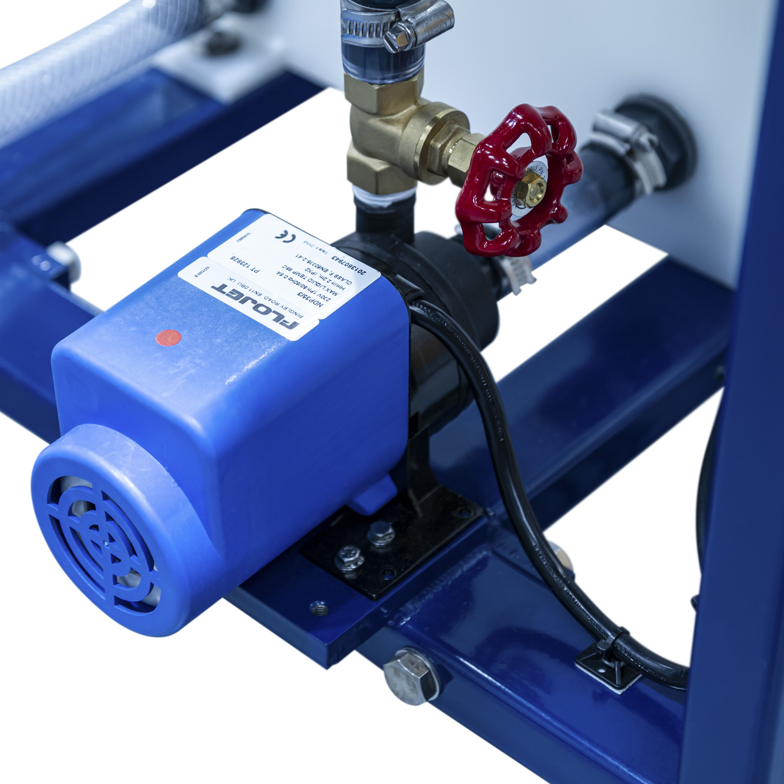
Adjustable overflows are provided close to each end of the tank so that constant water levels may be maintained in each half of the tank. These may be lowered to a position close to the bed of the tank for some experiments to provide subsoil drainage. The equipment is self-contained, requiring only an initial fill with cold water and connection to the electricity supply. The sump tank can be emptied to a laboratory drain.
Typical student experiments include:
- Seepage underneath a sheet pile wall
- Seepage through an earth dam
- Control of seepage through permeable soils by subsoil drainage
- Distribution of uplift pressure on hydraulic structures
- Reducing uplift pressure and lateral thrust by drainage
- Formation and behaviour of ‘quicksand’
- Stability of an earth dam
- Draining an excavation site using wells
Note that the tank is supplied without sand. (0.1m³ is required of washed, narrow range sand (coarse) with no fraction finer than 0.5mm)
Technical Specifications
Features & Benefits
Benefits
- A self-contained facility for study of flow through permeable media
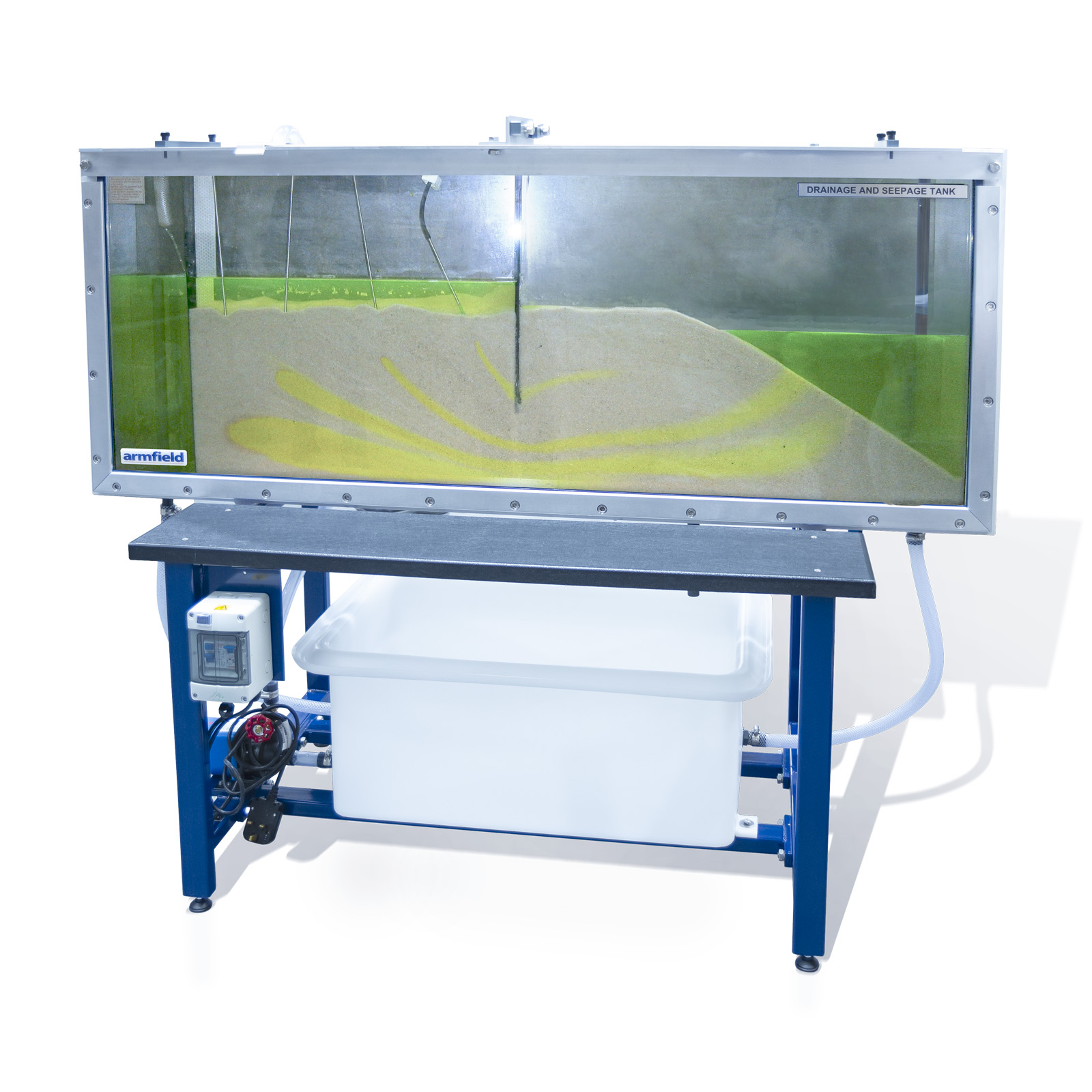
- The tank has a toughened glass front and aluminium back to permit the insertion of pressure tappings as required. Six tapping points are provided
- The design of the side supports allows free access to the interior with minimum sight obstruction
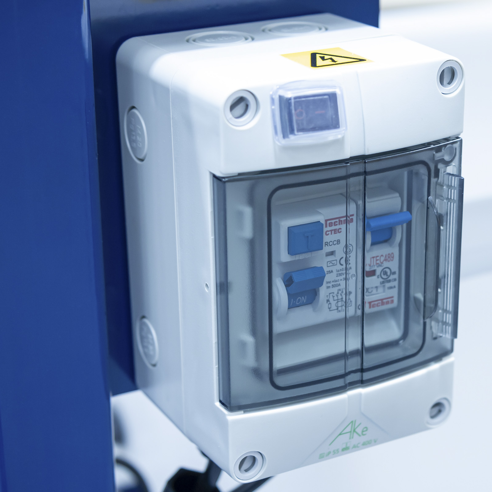
- Supply includes sump tank, pump, starter and control valve. As well as a dye injection system and a selection of models
- Comprehensive instruction manual with data sheets and student experiments
- Working section 1500mm x 100mm x 600mm

- Verification of Darcy’s law
- Flow net construction, flow lines and equipotential lines
- Determining seepage rates
- Boundary conditions
- Flow line visualisation
- Comparison of experimental results with analytical solutions
- Demonstrating seepage underneath a sheet pile wall
- Demonstrating seepage through an earth dam
- Demonstrating draining effect of a tile line
- Demonstrating draining effect of an open trench
- Demonstrating uplift pressure on foundation of structures
- Demonstrating changing uplift pressure by changing length of flow lines
- Demonstrating reduction of uplift pressure by draining
- Demonstrating reduction of lateral thrust on a retaining wall by draining
- Demonstrating quicksand
- Demonstrating stability of an earth dam
- Demonstrating well draining


- Foundation pressure plate
- Straight permeable membrane
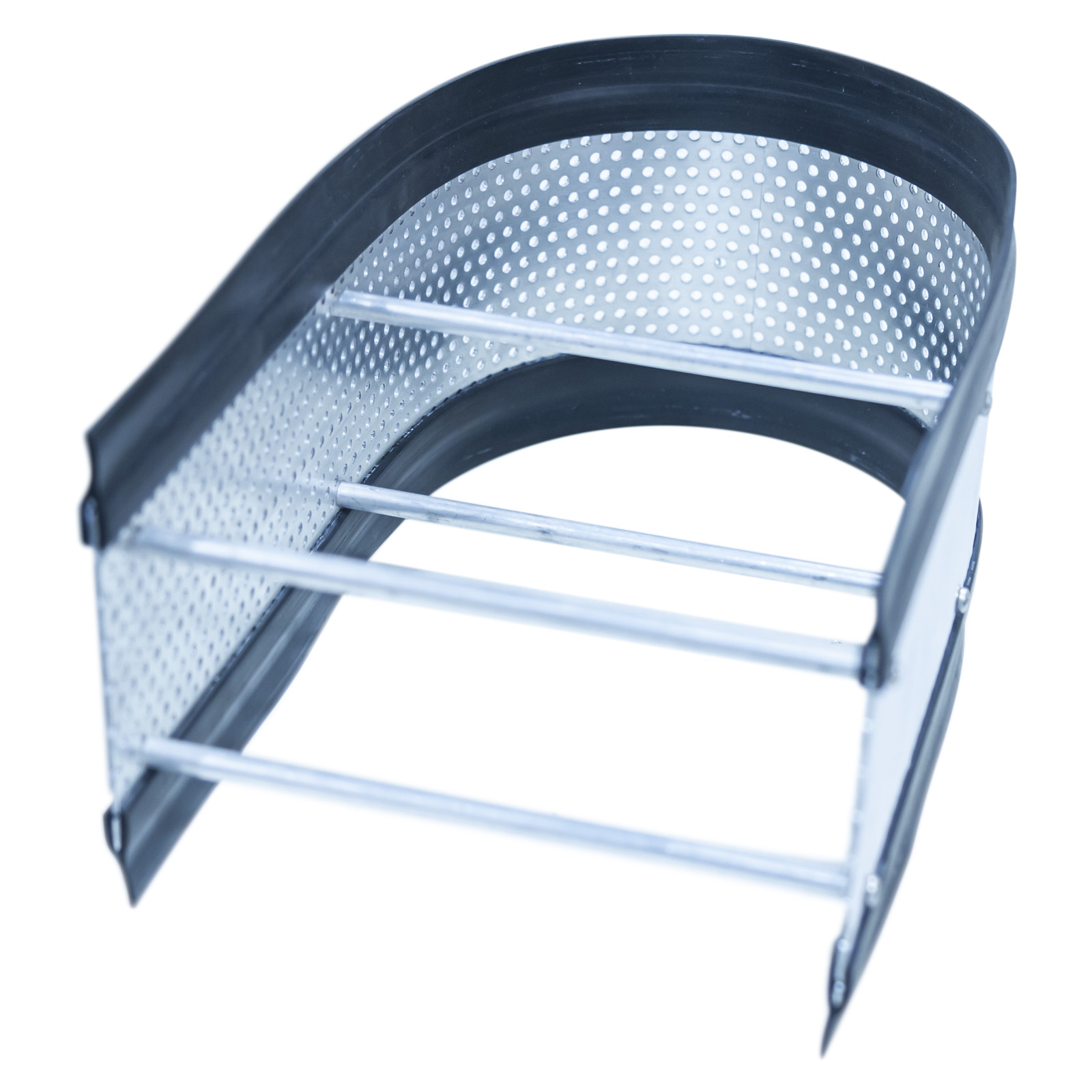
- Curved permeable membrane
- Lateral pressure plate
- Tile drain
Electricity supply:
S1-A: 220-240V/1ph/50Hz, 1A
S1-B: 120V/1ph/60Hz, 2A
S1-G: 220-240V/1ph/60Hz, 1A
PACKED AND CRATED SHIPPING SPECIFICATIONS
Volume: 2.4m³
Gross Weight: 270kg
Length: 1.60m
Width: 0.60m
Height: 1.45m
- S1-A
- S1-B
- S1-G