


F1-22-MKII Energy Losses in Bends and Fittings
This accessory permits losses in different bends, a sudden contraction, sudden enlargement and a typical control valve, to be demonstrated.
- Mitre bend – 90° elbow – Short and long bends
- Sudden contraction and sudden enlargement
- Fully Instrumented with upstream and downstream pressure tappings
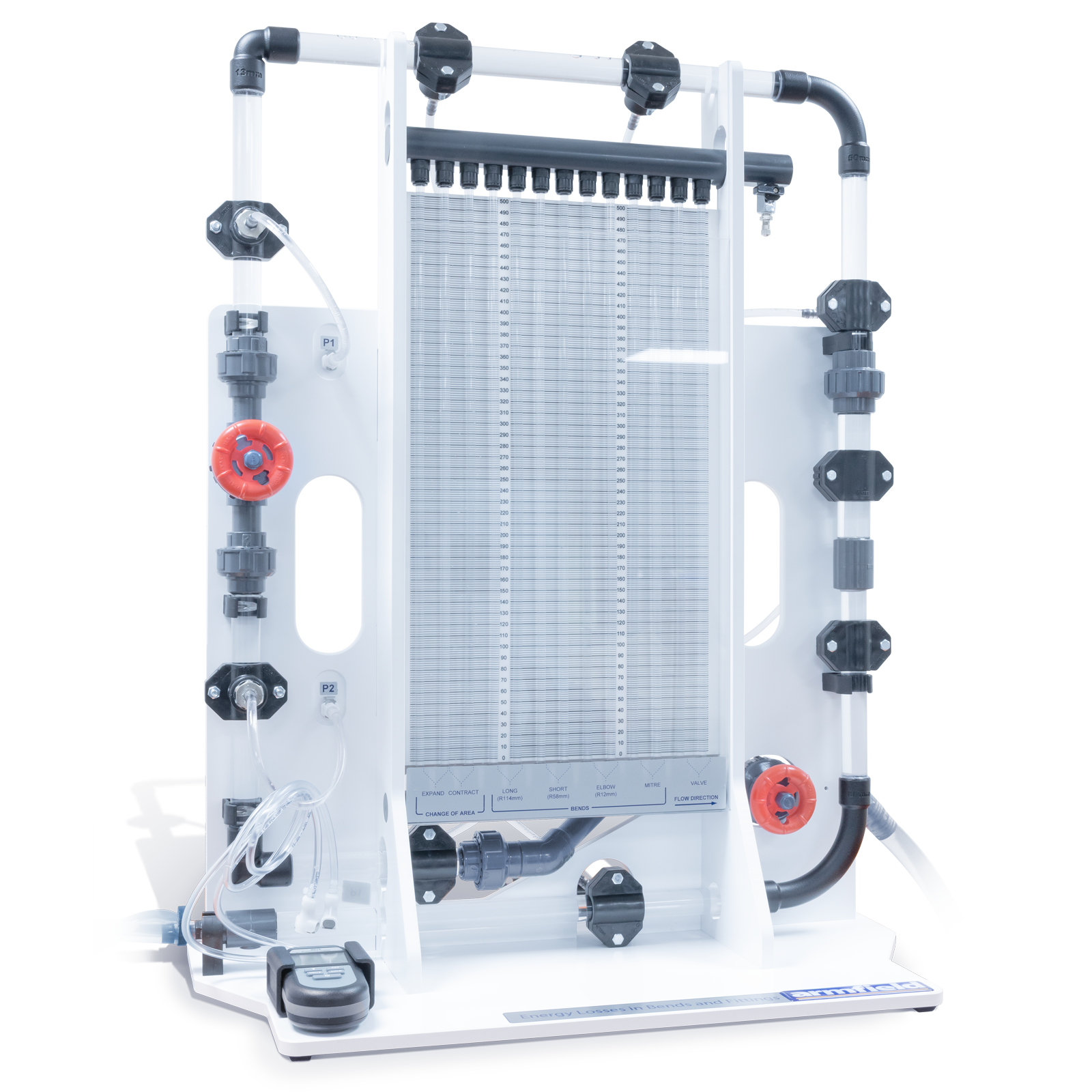
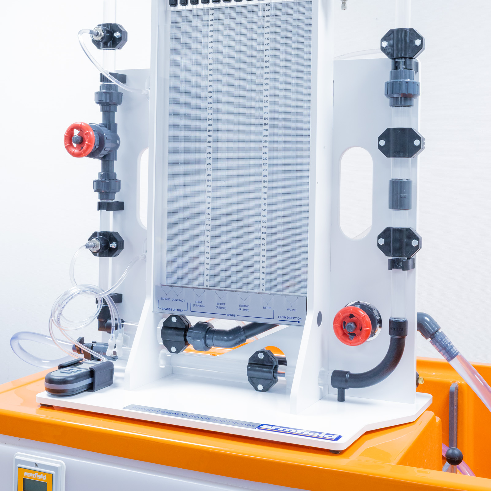
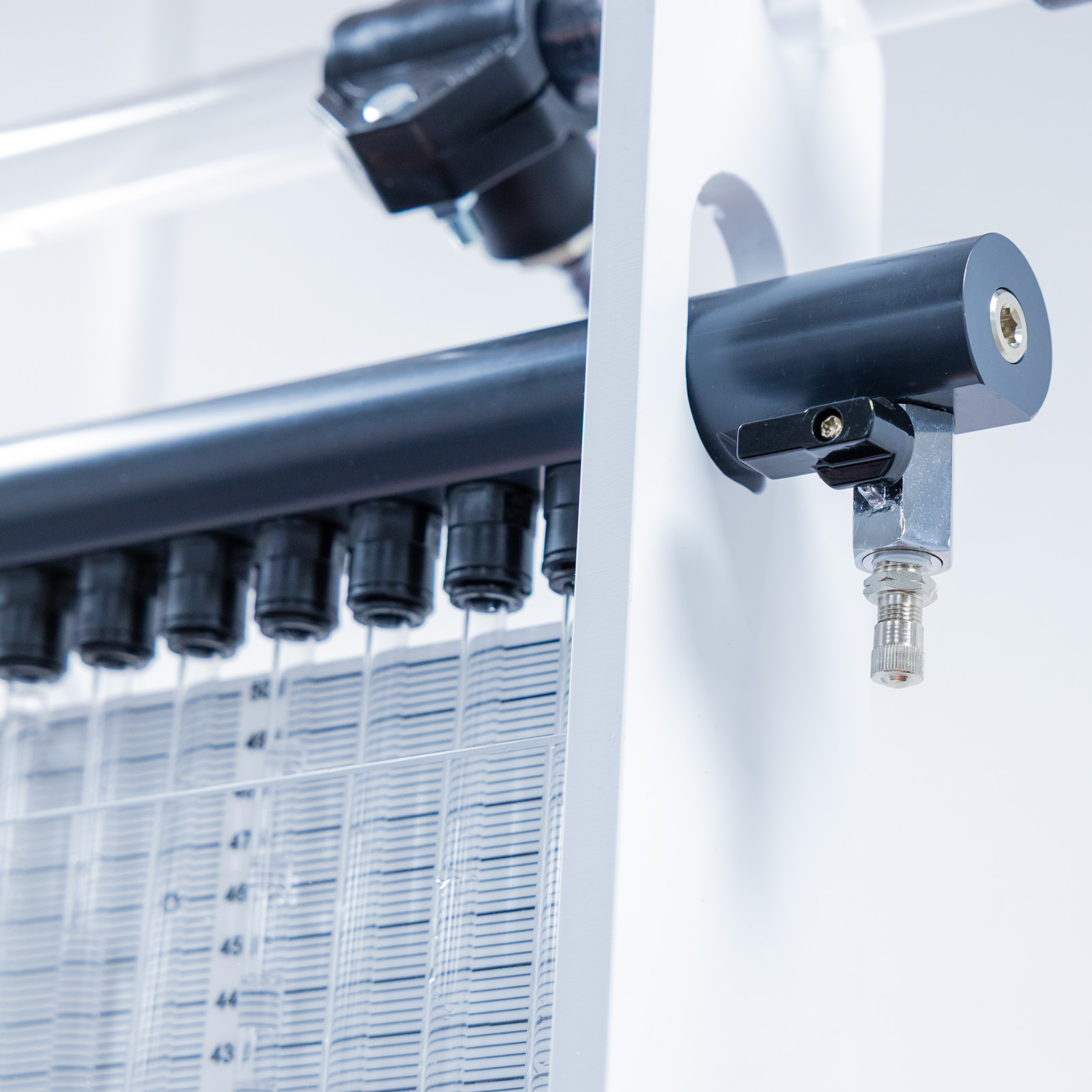
- A bank of 12 water manometer tubes, mounted on the framework for visualisation of the pressure drop profiles
Description
This accessory permits losses in different bends, a sudden contraction, sudden enlargement and a typical control valve, to be demonstrated.
- Mitre bend – 90° elbow – Short and long bends
- Sudden contraction and sudden enlargement
- Fully Instrumented with upstream and downstream pressure tappings
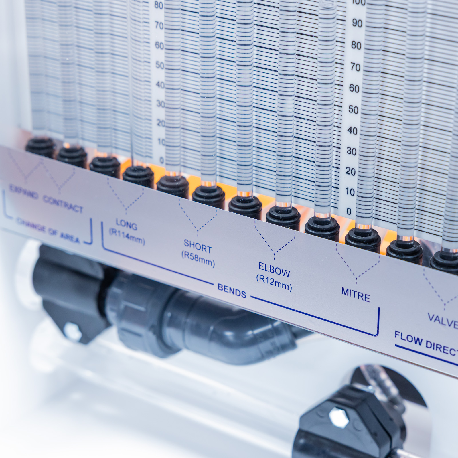
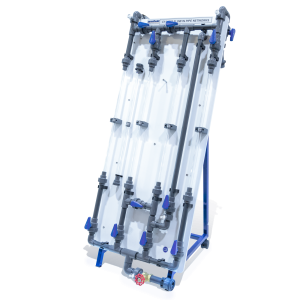
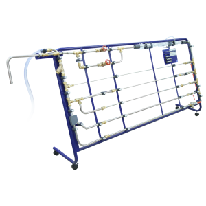
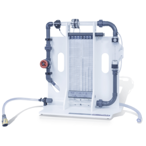
The equipment is mounted on a free-standing framework which supports the test pipework and instrumentation. The following typical pipe fittings are incorporated for study: mitre bend, 90° elbow, short and long bends sudden contraction and sudden enlargement.
All are instrumented with upstream and downstream pressure tappings. These tappings are connected to a bank of 12 water manometer tubes mounted on the framework. Pressurisation of the manometers is facilitated by a hand pump.
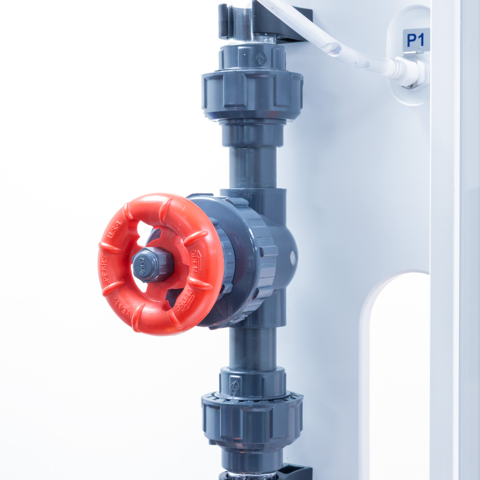
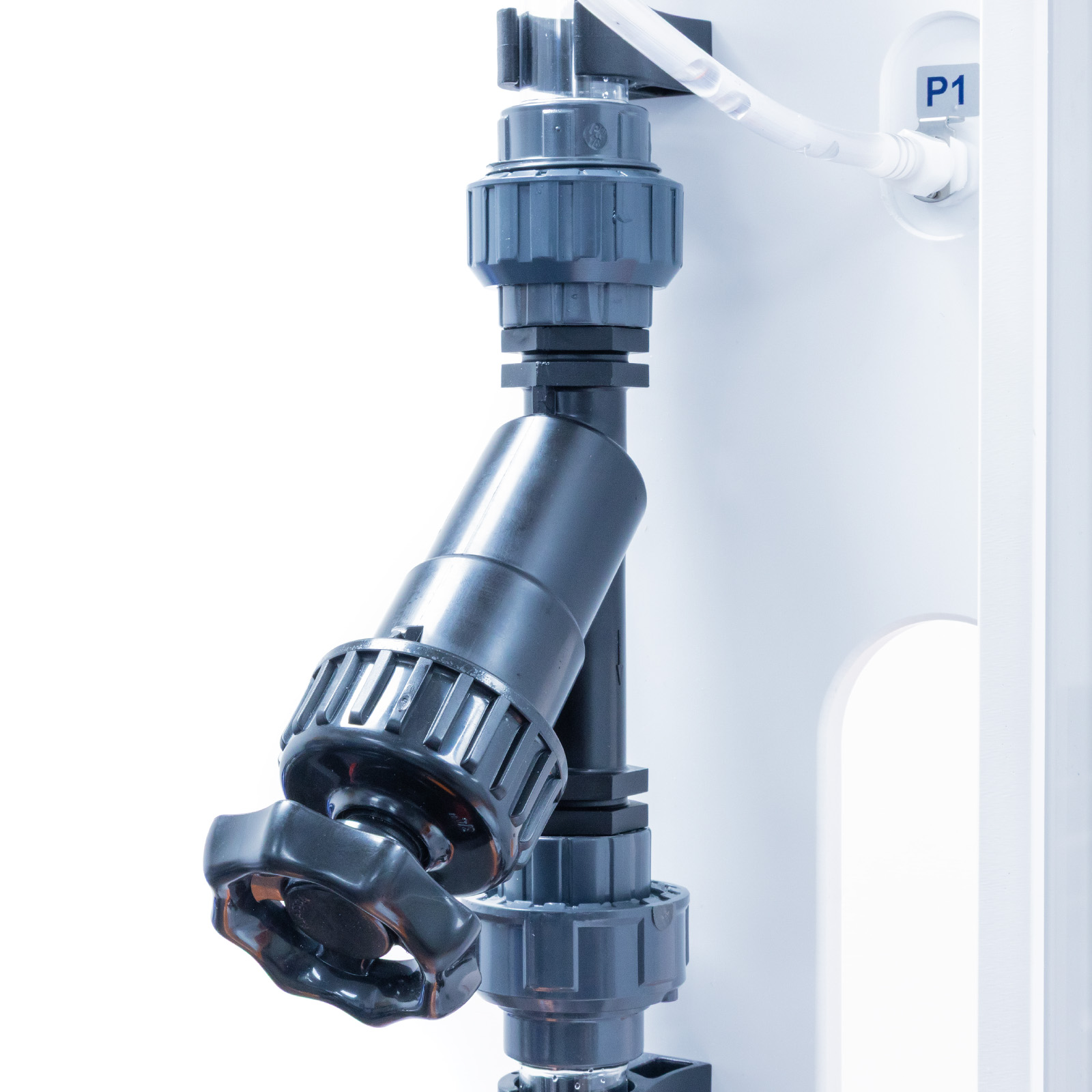
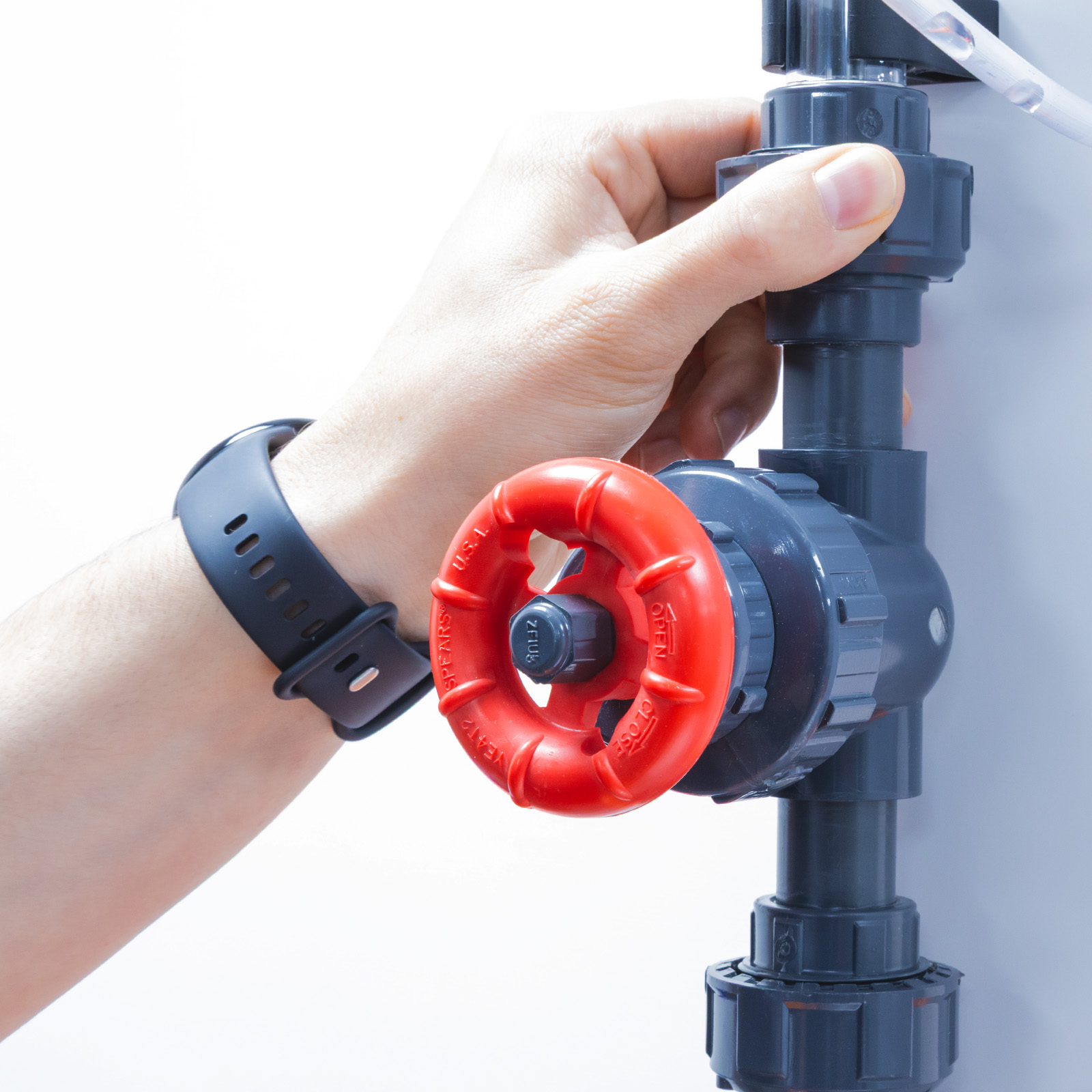
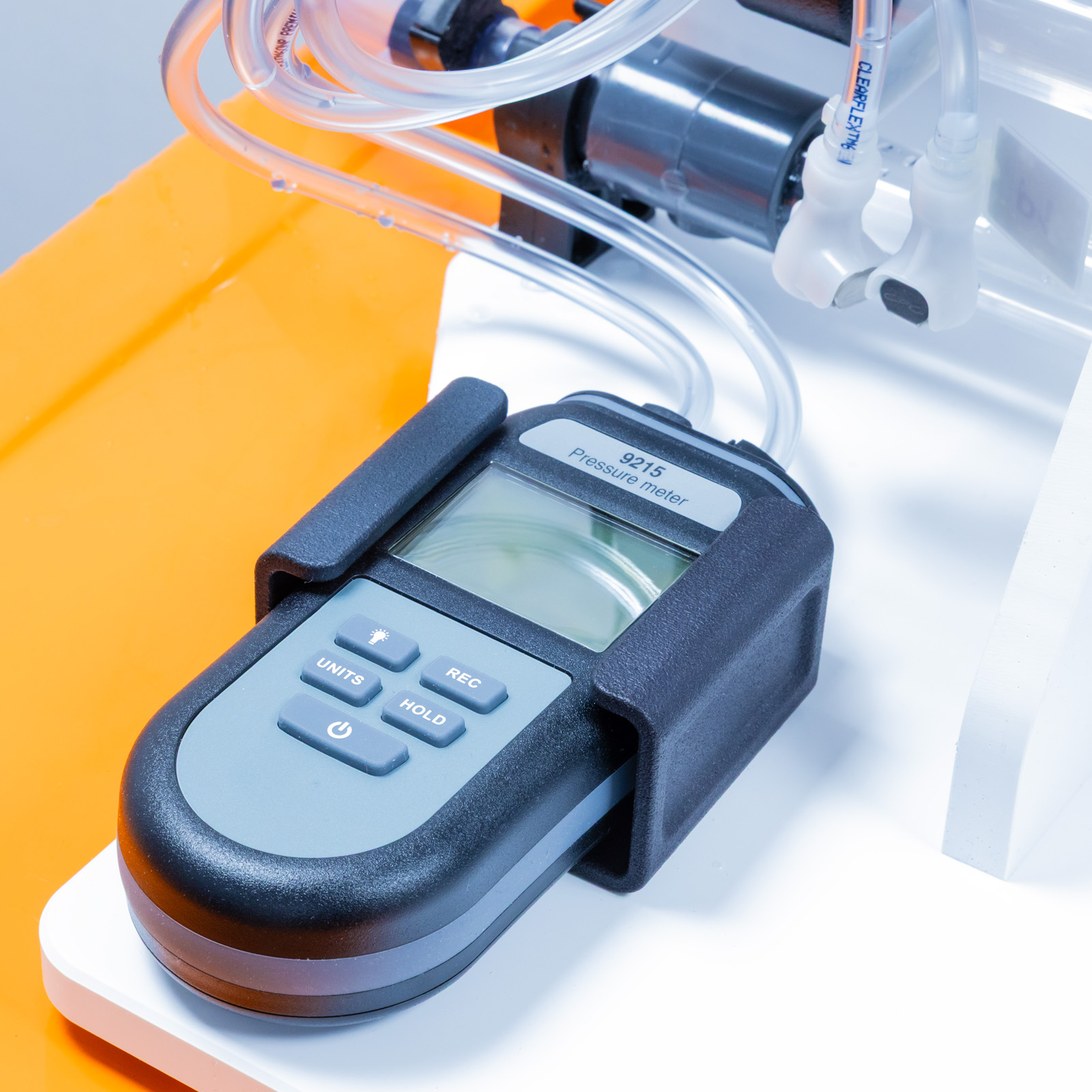
A separate gate valve is instrumented with upstream and downstream pressure tappings which are connected to a differential gauge on the edge of the framework. The gate valve can be replaced with two other valve types to further increase the experimental content. The unit stands on the working top of the hydraulics bench, which also serves as the water supply source.
Technical Specifications
- Pipe diameter: 19.48mm
- Differential pressure gauge: 0-3 bar
- Enlargement diameter: 26.2mm
- Contraction diameter: 19.48mm
- Fittings:
- short bend
- long bend
- elbow
- mitre bend
- area enlargement
- area contraction
- gate valve
- Additional Valves: Ball Valve / Angle Valve
- Manometer range: 0-440mm
- Number of manometer tubes: 12
- Differential manometers: 6
Features & Benefits

Supplied as standard: Measuring the losses in the devices related to flow rate and calculating loss coefficients related to velocity head including:
- Long bend
- Area enlargement
- Area contraction
- Elbow bend
- Mitre bend
- Short bend
- Gate valve fitting
- Comparing the pressure drop across each device
Length: 0.86m
Width: 0.34m
Height: 0.74m
- F1-22-MKII
- F1-22-MKII-1