


F1-18-MKII Energy Losses in Pipes
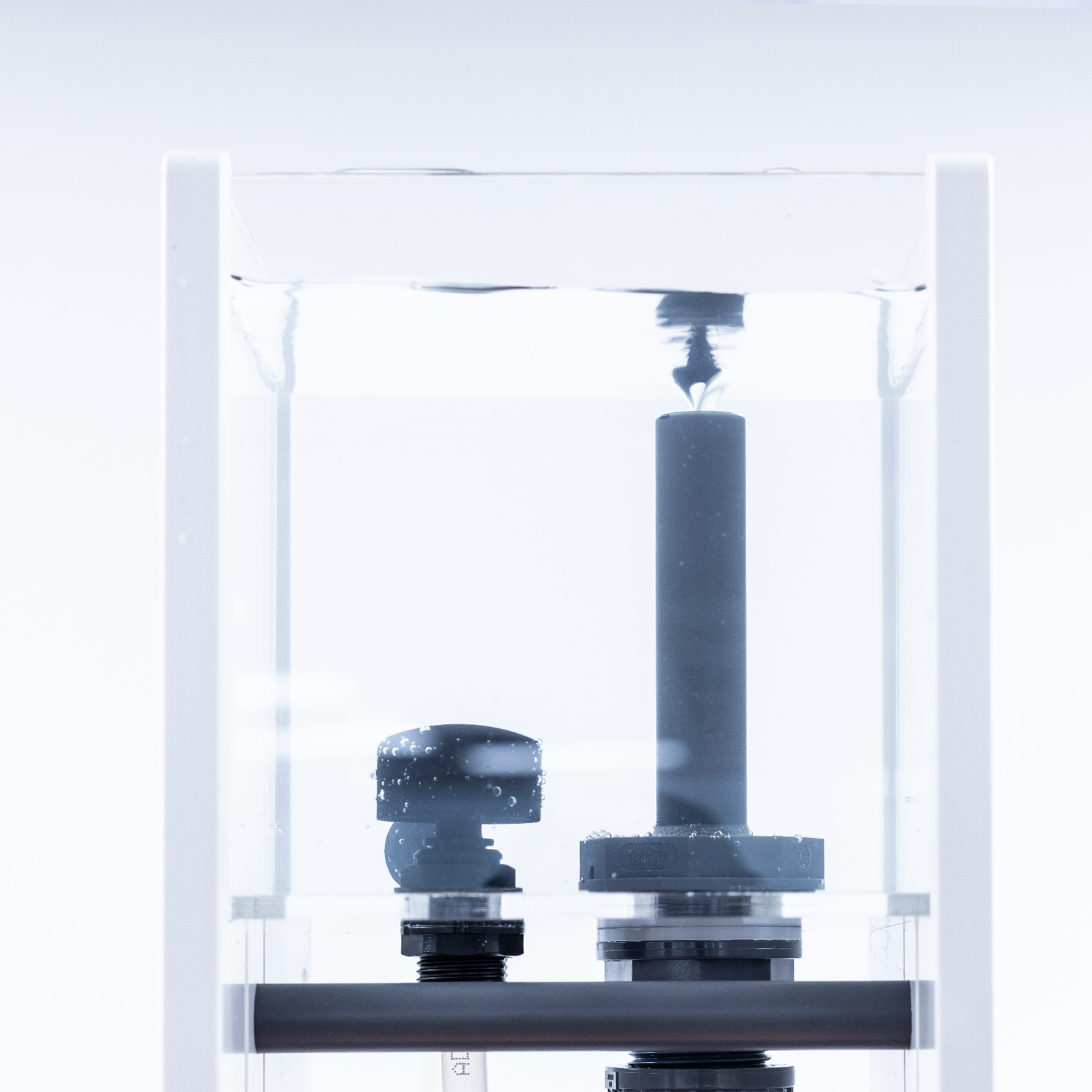
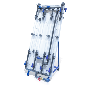
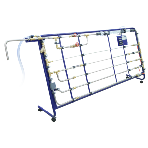
The unit consists of a vertical test pipe on the side of the equipment which can be fed directly from the hydraulics bench supply or, alternatively, from the integral constant head tank above.
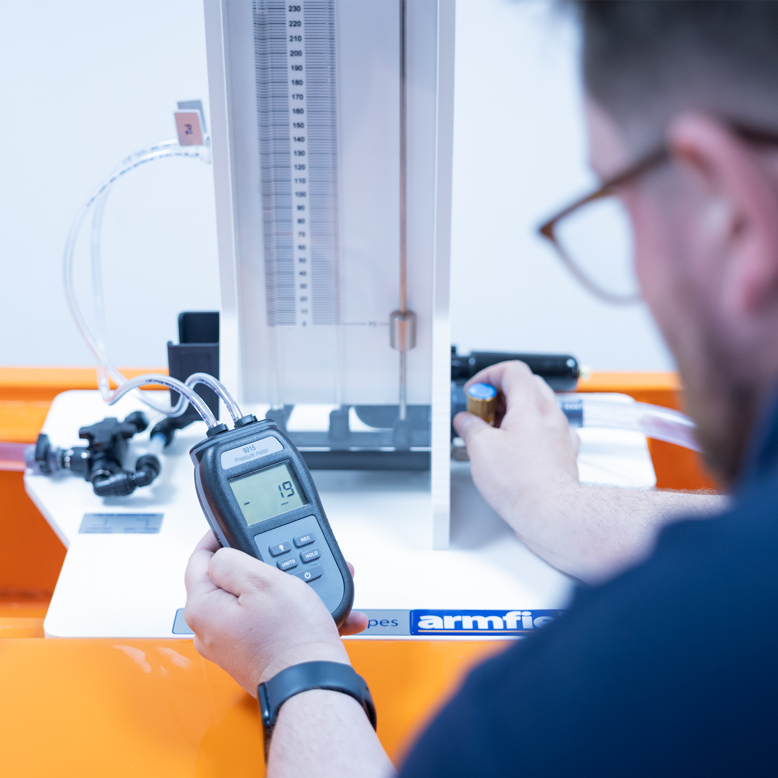
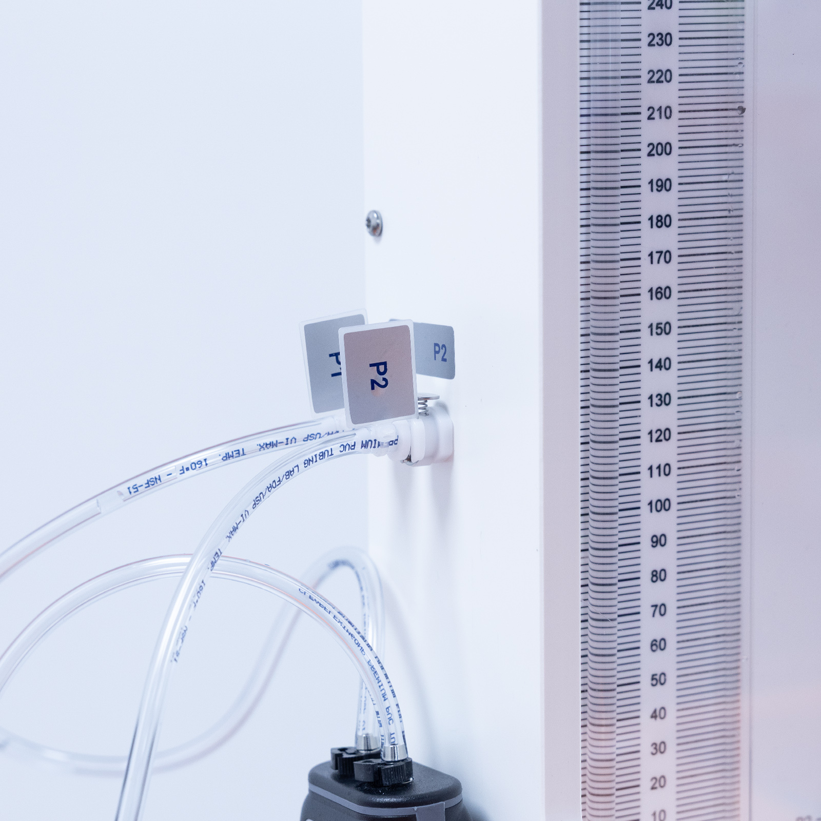
For large pressure differentials a digital handheld manometer is used.
Description
The unit consists of a vertical test pipe on the front of the equipment which can be fed directly from the hydraulics bench supply or, alternatively, from the integral constant head tank above.
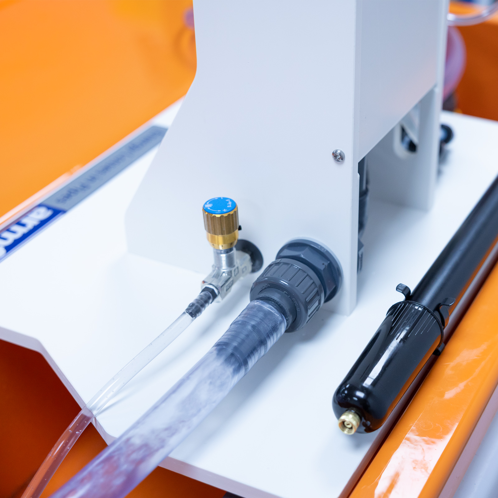
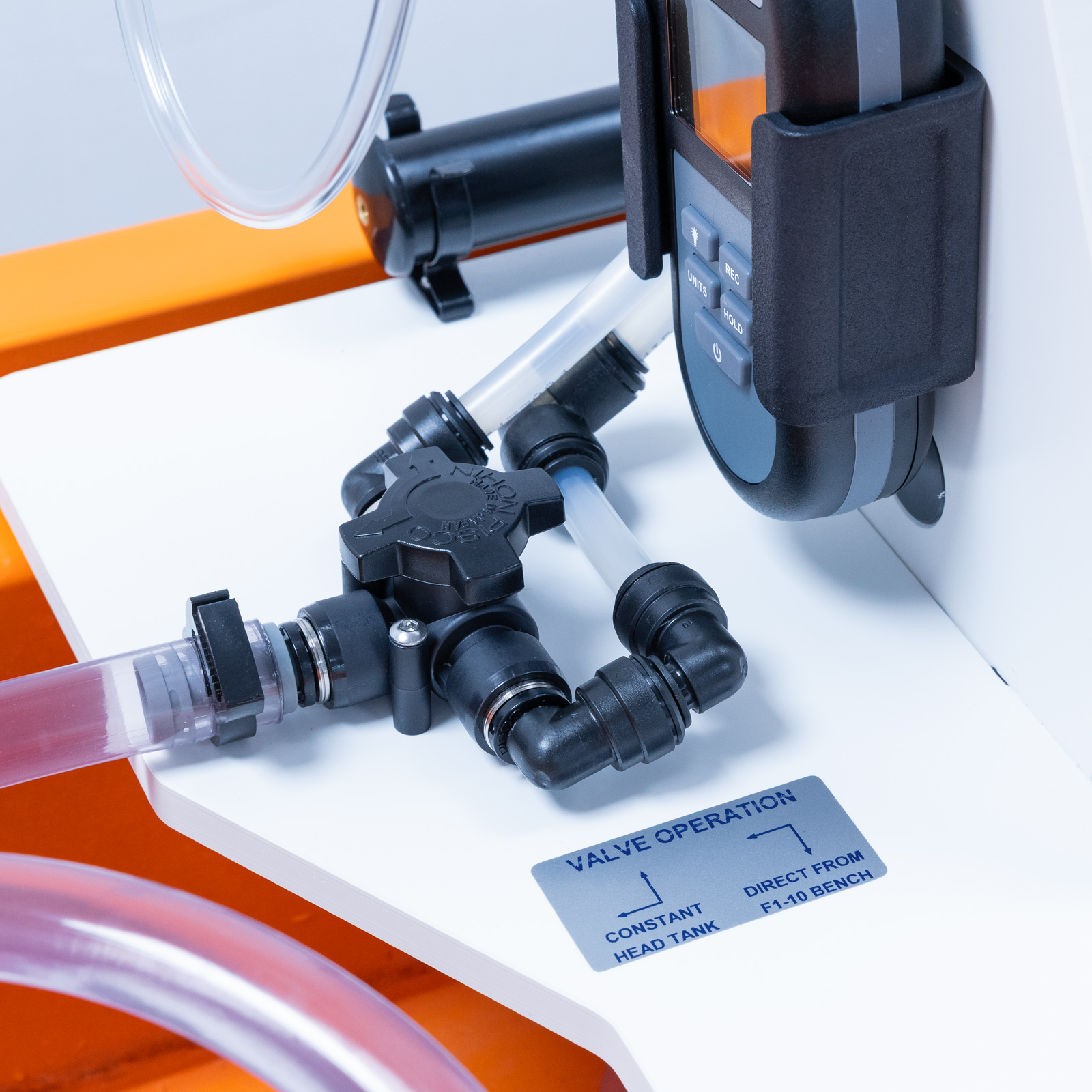
These in turn provide high or low flow rates which may be controlled by a valve at the discharge end of the test pipe. Manometers are used to measure the head loss.
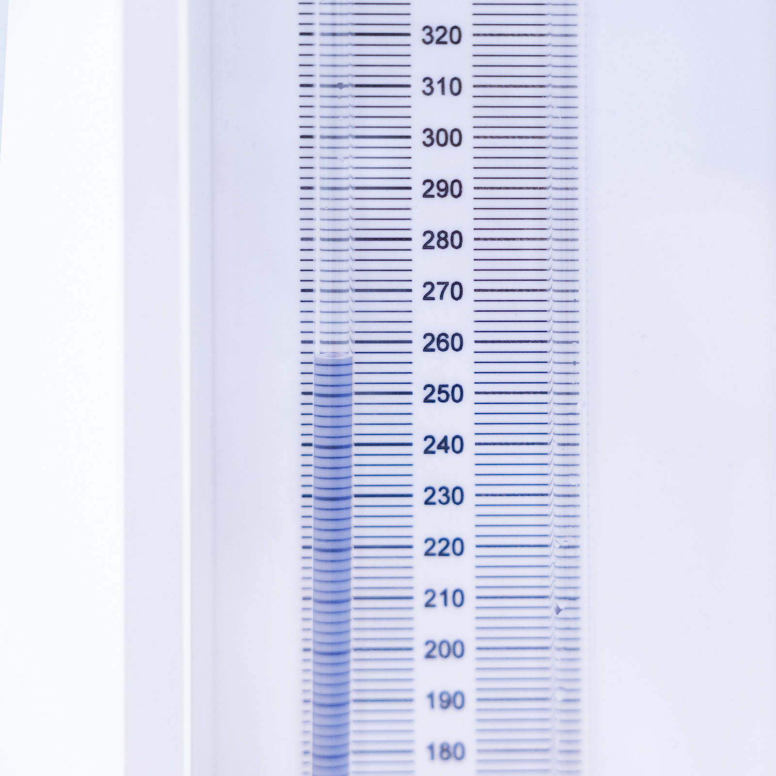
For large pressure differentials a digital handheld manometer is used. In addition, a pressurised water manometer for small pressure differentials
is also fitted to the unit.

Technical Specifications
Diameter of test pipe: 3.0mm
Length of test pipe: 674mm
Distance between pressure tapping points: 500mm
Range of digital manometer: 103 kPa
Range of water manometer: 500mm
Measuring cylinder capacity: 1000mm
Requires Hydraulics Bench Service unit F1-10/F1-10-2
Features & Benefits

- To investigate the head loss due to friction in the flow of water through a pipe and to determine the associated friction factor over a range of flow rates in laminar flow
- To investigate the head loss due to friction in the flow of water through a pipe and to determine the associated friction factor over a range of flow rates in turbulent flow
- Determining the critical Reynolds number
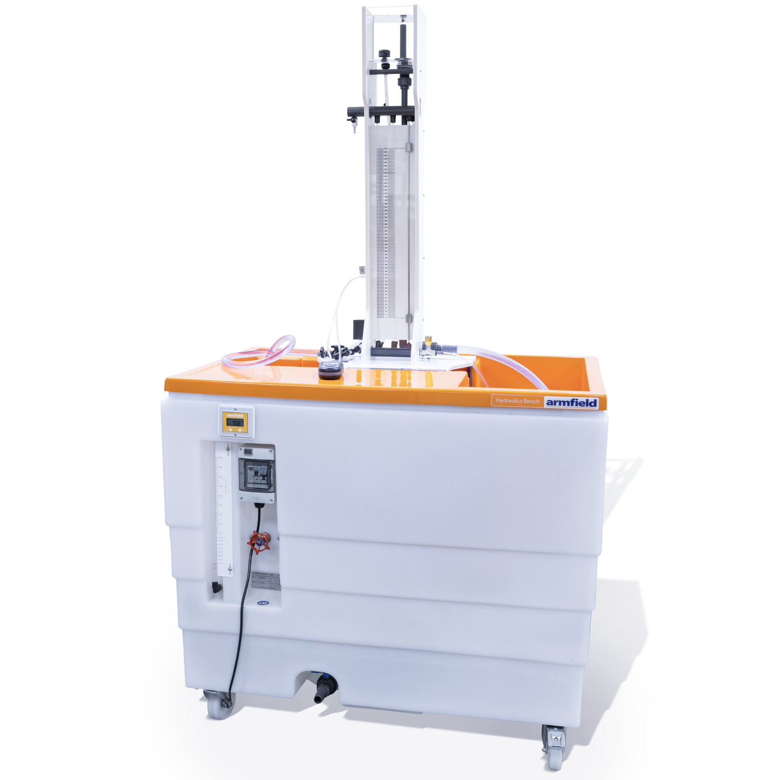
The Energy Losses in Pipes accessory consists of a test pipe, orientated vertically on the front of the equipment, which may be fed directly from the hydraulics bench supply or, alternatively, from the integral constant head tank.
These sources provide high or low flow rates which can be controlled by a valve at the discharge end of the test pipe. Head loss between two tapping points in the test pipe is measured using two manometers, digital hand-held manometer for large pressure differentials and a pressurised water manometer for small pressure differentials.
Excess water discharging from the constant head tank is returned to the sump tank of the hydraulics bench.
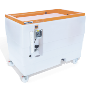
F1-10 Hydraulics Bench
Length: 0.34m
Width: 0.48m
Height: 1.04m
F1-18-MKII
