


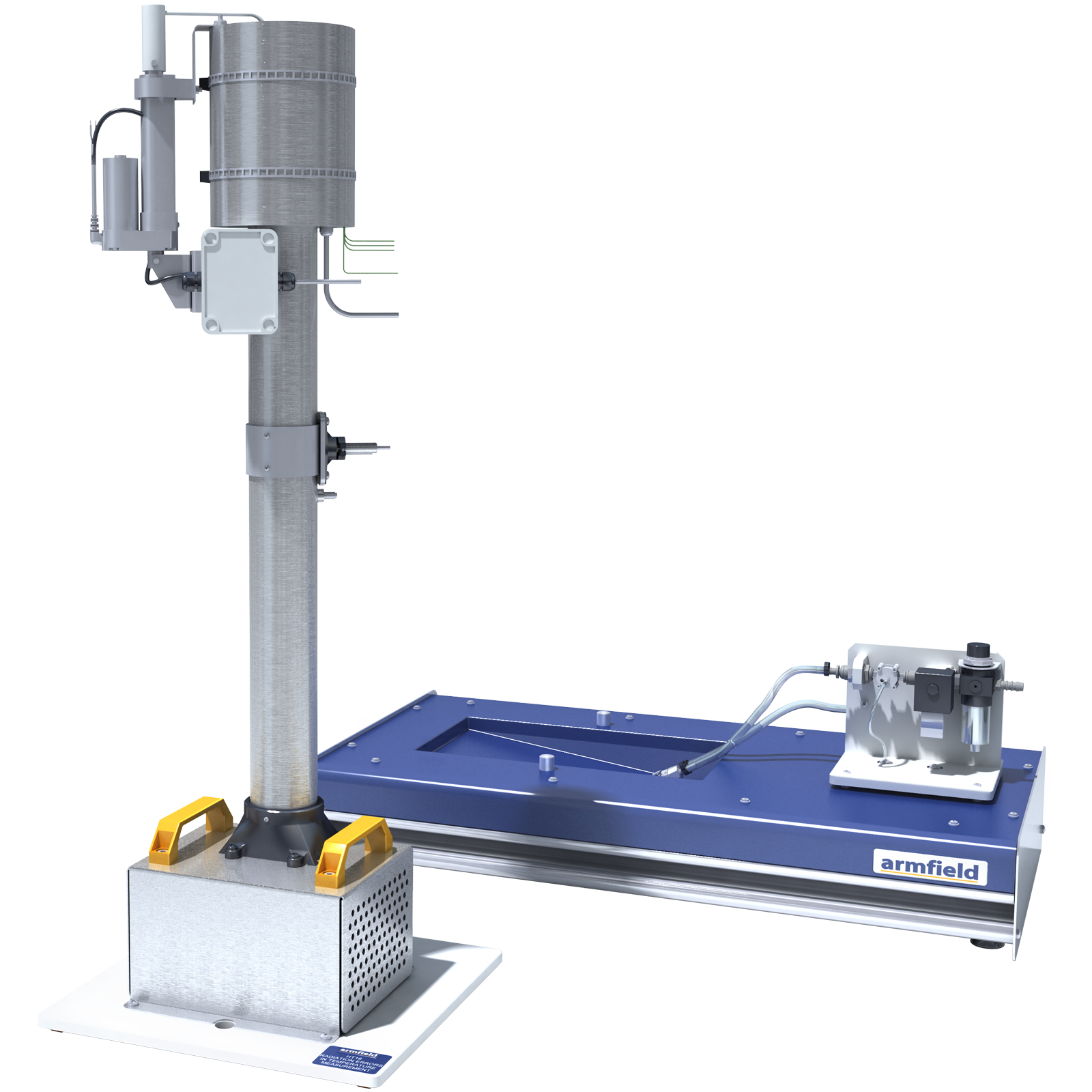

HT16X – Radiation Errors in Temperature Measurement
The ‘Radiation Errors in Temperature Measurement’ accessory comprises a tubular metal duct through which air, at ambient temperature, is blown vertically upwards by a centrifugal fan.
The velocity of the air can be changed by adjusting a throttle plate at the fan inlet and measured by an anemometer in the fan outlet duct.
Description
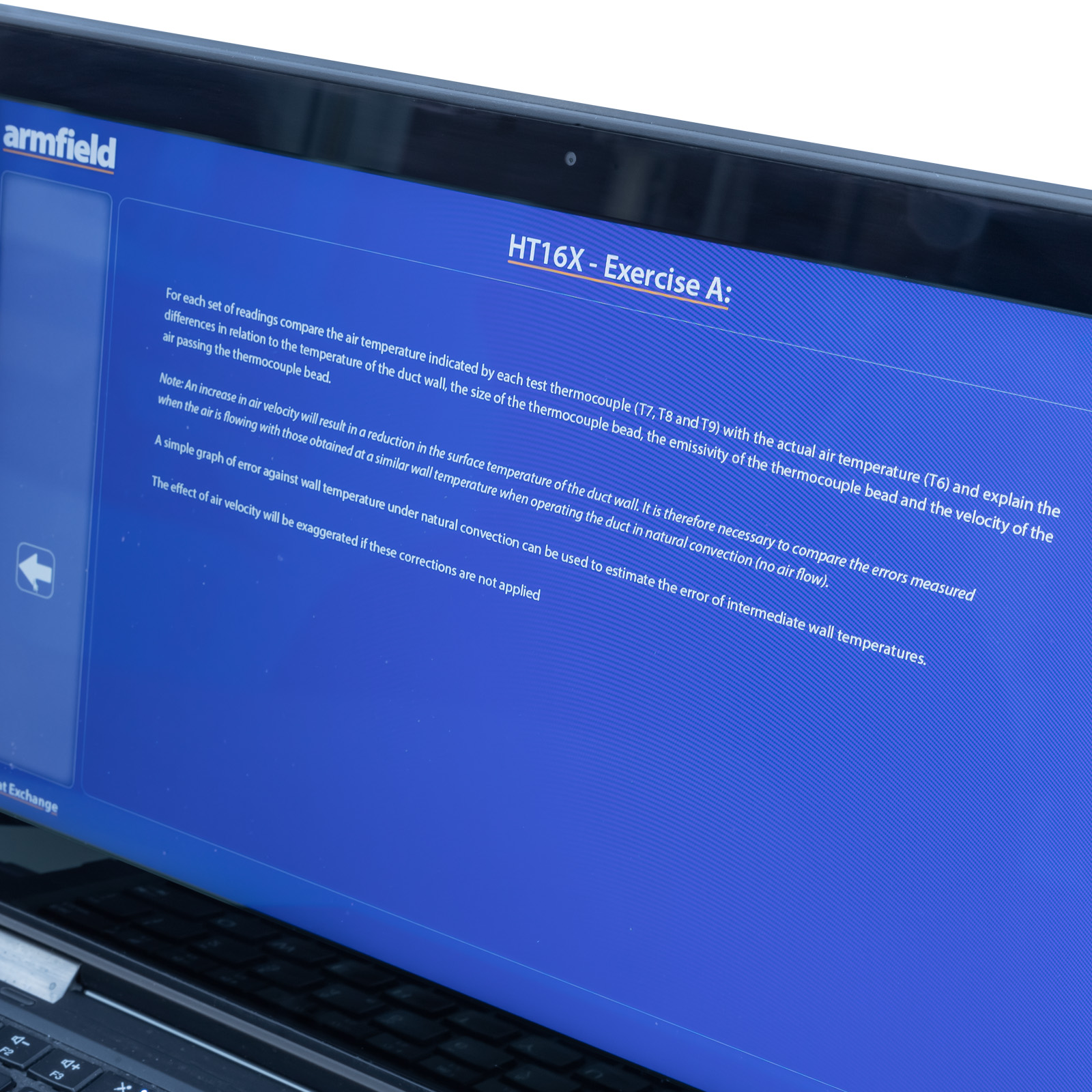
Radiative heat transfer between a thermometer and its surroundings may significantly affect temperature readings obtained from the thermometer, especially when the temperature of a gas is to be measured while the thermometer ‘sees’ surrounding surfaces at a higher or lower temperature than the gas.
The error in the reading from the thermometer is also affected by other factors such as the gas velocity over the thermometer, the physical size of the thermometer and the emissivity of the thermometer body. In this equipment a group of thermocouples are used to measure the temperature of a stream of air, at ambient temperature, passing through the centre of a duct while the wall of the duct is elevated in temperature to subject the thermocouples to a source of thermal radiation.
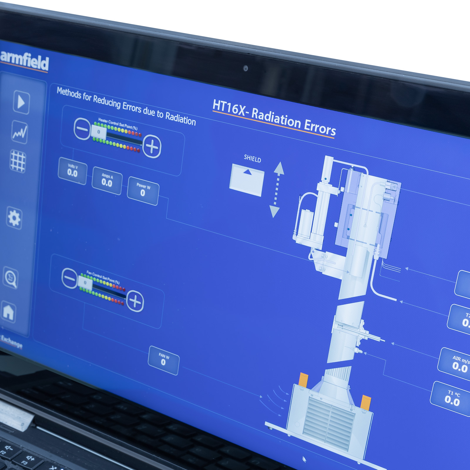
Each thermocouple gains heat by radiation from the heated wall and loses heat by convection to the air stream and conduction along the wire. The net result is an increase in the temperature of the thermocouple above the temperature of the air stream it is supposed to measure. The result is an error in the reading from the thermocouple. A radiation shield can be positioned in the duct to show the effect of screening the thermocouples from thermal radiation from the duct wall.
The effect of air velocity past the test thermocouples can be demonstrated by adjusting the air flow. This is achieved by a variable speed fan controlled using the software, by adjusting the power supplied or using a PID controller to automatically achieve air velocity set-point.
A vane-type anemometer within the fan outlet duct enables the air velocity through the heated section to be measured.
A radiation shield, which remains close to the air temperature, can be raised or lowered over the thermocouples to demonstrate the change in readings when a radiation shield is used. This radiation shield is controlled by an electro-mechanical servo actuator under software control.
Technical Specifications
- A small-scale accessory to demonstrate how temperature measurements can be influenced by sources of thermal radiation
- Comprises three K-type thermocouples with different styles of bead mounted in a vertical air duct. A fan at the base of the duct provides a variable air flow over the cylinder. A band heater heats the duct wall adjacent to the thermocouple beads
- Heater rating 216W at 24V DC
- K-type thermocouples measure the air temperature upstream and the surface temperature of the heated duct section
- Air flow is electronically adjustable over the range of 0-9 m/s by a variable-speed centrifugal blower
- Heater and centrifugal blower are software adjustable.
- The air flow rate is measured by a vane-type anemometer in the outlet duct
- A radiation shield can be lowered over the thermocouples to demonstrate the improvement in reading accuracy when the thermocouples are shielded from the source of radiation
- The accessory is mounted on a PVC baseplate, which is designed to stand on the benchtop and connect to the Heat Transfer Service Unit without the need for tools
- A comprehensive instruction manual is included

Features & Benefits

- Errors associated with radiative heat transfer:
– Effect of wall temperature on measurement error
– Effect of air velocity on measurement error
– Effect of thermocouple style on measurement error
- Methods for reducing errors due to radiation:
– Design of a radiation-resistant thermometer
– Use of a radiation shield to surround the thermometer
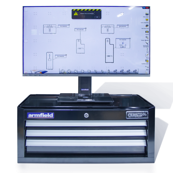
A full armBus educational software suite is provided with the HT10X for all the Armfield heat transfer accessories.
Individual experiment interfaces and displayed data types vary to match selected experiment accessories, common examples are listed below:
- Temperatures and other signals such as flow rates, heater voltage and current are displayed on a diagrammatic representation of the equipment
- Control outputs are operated by a control slider or typing in a value between 0 and 100%. Sensor values are read directly in engineering units
- PID automatic control option is available, permitting the temperature set-point to be achieved quickly and precisely, coping with disturbance rejection
- A maintenance screen allows for PID parameter adjustment and thermocouple calibration
- Data from the sensors are logged into a spreadsheet format, with operator control over the sampling intervals (or ‘single-shot’)
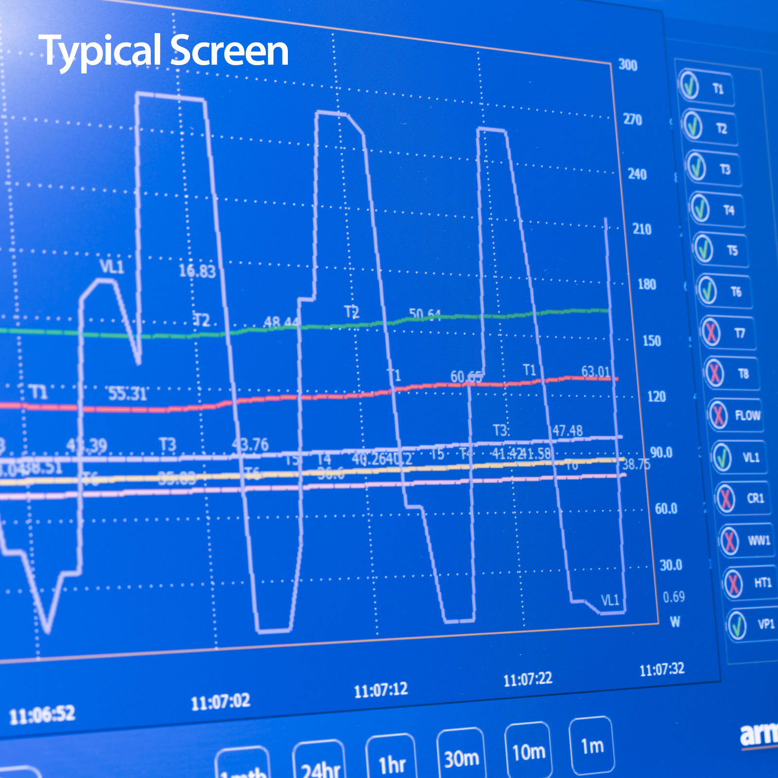
- Sophisticated graph-plotting facilities are provided, including plotting of both measured and calculated values
- Graphs update in real-time as the samples are being taken
- Processing of measured values to obtain calculated values is linked to the questions and answers to ensure student understanding
- Experiment data samples are saved, or exported in Microsoft Excel format
- Real-time sensor data is displayed independently from the data logging. It is possible to check the recent history graphical display to inspect the temperature stability prior to taking a sample

- HT10X Computer-Controlled Heat Transfer Service Unit
HT10X Computer-Controlled Heat Transfer Service Unit
(All electrical requirements are obtained from the service unit)
Packed and crated shipping specifications
Volume: 0.2m3
Gross weight: 28kg
Length: 0.35m
Width: 0.30m
Height: 1.22m
HT16X