


EF-3.4 – Mechanisms – Bar Linkages
The EF-3.4 Bar Linkages experiments kit comprises of different bars or links configured into a range of different linkage mechanisms, including four-bar linkages. Rotary, linear movement and planar linkages allowing students to trace the relative movements of each linkage and joint.
A linkage is an assembly of links and joints that provide a desired output motion in response to a specified input motion.
Description
The Engineering Fundamentals range enables students to gain an understanding of the principles of engineering by the process of learning via experimentation.
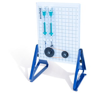
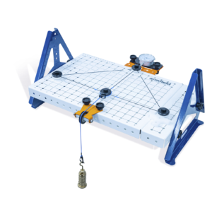
The EF-3.4 Bar Linkages experiments kit comprises of different bars or links configured into a range of different linkage mechanisms, including four-bar linkages, rotary and linear movement and planar linkages allowing students to trace the relative movements of each linkage and joint.
A linkage is an assembly of links and joints that provide a desired output motion in response to a specified input motion.
One such example and one of the simplest moveable closed-chain linkages is the four-bar which consists of four bars or links connected in a loop by four joints and can be used for many mechanical purposes including converting rotational motion to reciprocating motion and converting reciprocation motion to rotational motion.
Technical Specifications
Features & Benefits
Features
- Neatly presented in an easily identifiable and durable storage tray
- Trays have clear lids making it easy to see their contents
- Pictorial tray contents list to identify missing components easily
- Accompanied by a detailed manual with various practical exercises
- Clear and concise assembly instructions for each experiment
- Multiple experiments per kit
- Toolless assembly
Benefits
- Hands-on understanding from lessons
- Improve the student’s dexterity by self-assembly with the instructions provided

- Four-bar linkages – crank rocker, double rocker, drag link and parallelogram
- Determine degrees of freedom of a four-bar linkage
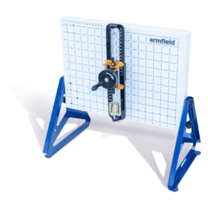
- Straight line linkages – Watt’s straight line, Chebyshev, Peaucellier- Lipkin, Hart’s inversor and Hoeken’s
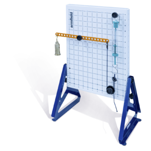
- The different ways motion is transferred from one motion to another. For example, linear to rotary and linear to rocking
- The different motions scribed by different locations on a bar linkage system
- What is meant by constrained motion?
- Pantograph
- Ackermann steering
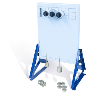
- EF-BU Base Unit
- Statics Experiments
– EF-1.1 Forces
– EF-1.2 Moments
– EF-1.3a Beams
– EF-1.3bTrusses
– EF-1.4 Springs
– EF-1.5 Torsion
- Dynamics Experiments
– EF-2.1 Friction
– EF-2.2 Simple Harmonic Motion
– EF-2.3 Rotational Friction
– EF-2.4 Potential and Kinetic Energy
– EF-2.5 Centrifugal and Centripetal Force
- Mechanisms Experiments
– EF-3.1 Cam, Crank and Toggle
– EF-3.2 Simple Mechanisms
– EF-3.3 Additional Mechanisms
– EF-3.4 Bar Linkages
- Kinematics
– EF-4.1 Pulleys
– EF-4.2 Gears
– EF-4.3 Drive Systems
- Strength of Materials
– EF-5.1 Tensile Tester
- Options
– EF-WS Workstation
- 2 x 13 Hole linkage
- 4 x 9 Hole linkage
- 2 x 7 Hole linkage
- 4 x 5 Hole linkage
- Removable pivot pin – short, medium, long
- Stand – short, medium, long
- EF-BU Base Unit
- EF-BU on which to build the experiment from the tray components
- Level and stable work surface to mount the EF-BU upon. The optional EF-WS is ideal for this if no suitable desk or bench is available.
Volume: 0.02m³ per tray
Gross Weight: 5.0kg per tray
Tray
Length: 0.430m per tray
Width: 0.312m per tray
Height: 0.080m per tray
- EF-3.4 – Bar Linkages
- EF-BU – Base Unit
- EF-WS – Workstation (optional)
