


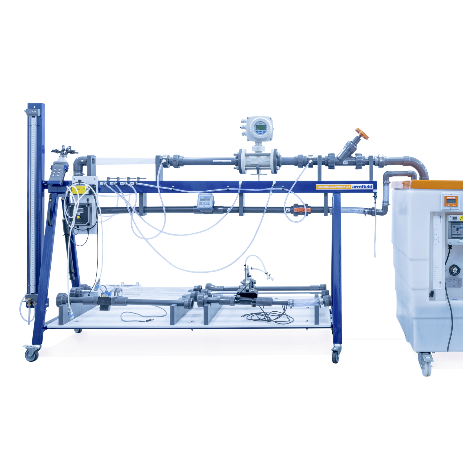


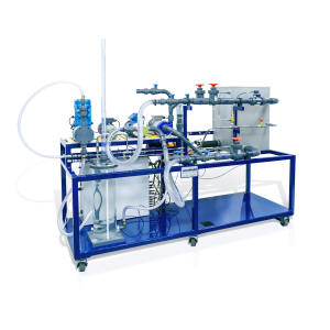
C9-MKII Flowmeter Demonstrator
The C9-MKII- Flowmeter Demonstrator is designed to allow the user to understand aspects about the different types of flowmeters commonly found in use throughout various industries.
The flowmeters available are of both electronic and non-electronic types with the options covering both mechanical and passive systems.
The unit is supplied with armBUS software as standard. Including manual data entry for non electronic flow meters and automatic datalogging for electronic flow meters. (Requires AIU-4)
Description
The C9-MKII Flowmeter Demonstrator is designed to allow the user to understand the different types of flowmeters commonly found in use throughout various industries.
The flowmeters available are of both electronic and non-electronic types with the options covering both mechanical and passive systems.
The experimental content includes the measurement of pressure loss across a range of flowmeters and the direct use of flowmeters for the determination of flowrates, either visually or by the use of pressure differential. The unit is supplied with armBUS software as standard. Including manual data entry for non electronic flow meters and automatic datalogging for electronic flow meters. (Requires AIU-4)
The unit can be used to:
- Understand the practical use and characteristics of Industrial flowmeters
- Assess the pressure drop which occurs with flowmeters within a simple piped system
- Understand flow measurement by using flowmeters which relay on a pressure change across the system
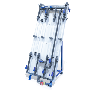
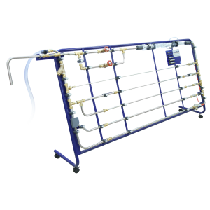
- The unit comprises of a framework that incorporates pipework with valves, a reference flowmeter, water and digital manometers and a test section for the insertion of flowmeters undergoing testing. The unit is designed to utilise the Armfield F1-10 Hydraulics Bench which provides a pumped reservoir of water to recirculate through the C9-MKII unit making efficient use of water. The flow rate of the system can be varied by use of a simple control valve to study the effects of changing flow in relation to pressure loss in a flowmeter
- The optional AIU4 Interface Console links the flowmeters with electronic outputs to the laptop or PC. The console interprets the signals received into the correct output format for the armBUS™ software. The console has a 24vDC power supply to reduce the risk of high voltage incidents with contact with water
Technical Specifications
- Digital Differential Manometer Operating range – 0 – 2000 mBar (0 – 1500mmHg)
- Water Manometer – Operating range – H12-2 1000 mm H2O
- Electromagnetic Flowmeter – 50 – 200 ltr/min.
- Ultrasonic Flowmeter – 5 – 240 ltr/min.
- Venturi Nozzle
- Pitot Tube
- Orifice Plate Flowmeter
- Paddle Wheel Flowmeter – 15 – 150 ltr/min.
- Turbine Wheel Flowmeter – 15 – 150 ltr/min.
- Variable Area Flowmeter – 10 – 100 ltr/min.
- Variable Area Flowmeter with Transducer – 15 – 150 ltr/min.
- Vortex Flowmeter – 8.3 – 133 ltr/min.
- Orifice Plate Flowmeter with Transducer – 30 – 150 ltr/min.
- Bypass Flow Meter – 20 – 100 ltr/min.
- Baffle Plate Flow Meter – 15 – 150 ltr/min.
- AIU4 unit – Supplied with Hall counter input, 4-20mA signal input, 0-5v signal input, USB Out
Features & Benefits
Modular Flow meter demonstration unit optionally supplied with 13 flowmeters
- Utilises Armfield F1-10 Hydraulics bench
- Allows students to understand the advantages and disadvantages of various flowmeters
- Asses the pressure drop which occurs with flowmeters within a simple piped system
- Understand the practical use and characteristics of Industrial flowmeters
- Supplied with Armbus software as standard
- Understand flow measurement by using flowmeters which relay on a pressure change across the system

- Comparing the use, application and limitations of various types of flow meter
- Considering the implications of flow meter selection on performance, accuracy, convenience, cost and head loss
- To demonstrate the use of one or more alternative flowmeters for the measurement of flow rate in a closed conduit, and to determine the flowmeter characteristics, primarily the pressure drop across the meter as well as it’s functionality
- Understanding the principles on which different types of flow meter are based
- Using manometers to measure pressure drop
- I nvestigating the effect of air in the hydraulic stream on flow meter performance
- Understanding the application of Bernoulli’s Theorem
- To demonstrate the application of an Orifice Plate, Venturi and Pitot tube in the measurement of flow rate in a closed conduit
- To demonstrate the use of one or more flowmeters for the measurement of flow rate in a closed conduit, and to determine the flowmeter characteristics. Including Electromagnetic, Ultrasonic, Paddle Wheel, Turbine Wheel, Variable Area with a Transducer, Vortex Flowmeter, Orifice Plate Flowmeter with Transducer, Bypass and Baffle Plate
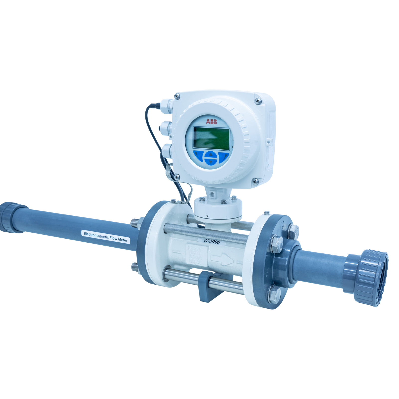
C9-MKII-1: Electromagnetic Flowmeter
The C9-MKII-1 Electromagnetic Flowmeter is a precision measuring device for determining the flow rate of almost any electrically conducting liquid and can include substances such as pulps, pastes and sludge’s.
The flowmeter will not work with non-conductive liquids such as high-quality distilled water and hydrocarbons as examples. The electromagnetic flowmeter is classed as a volumetric flowmeter.
One of the main advantages is the flowmeter has no moving parts and has a very low pressure drop. Electromagnetic flowmeters work on the principle of Faraday’s law of induction.
Supplied with direct datalogging via the supplied armBUS™ software (requires AIU-4 as an essential accessory)

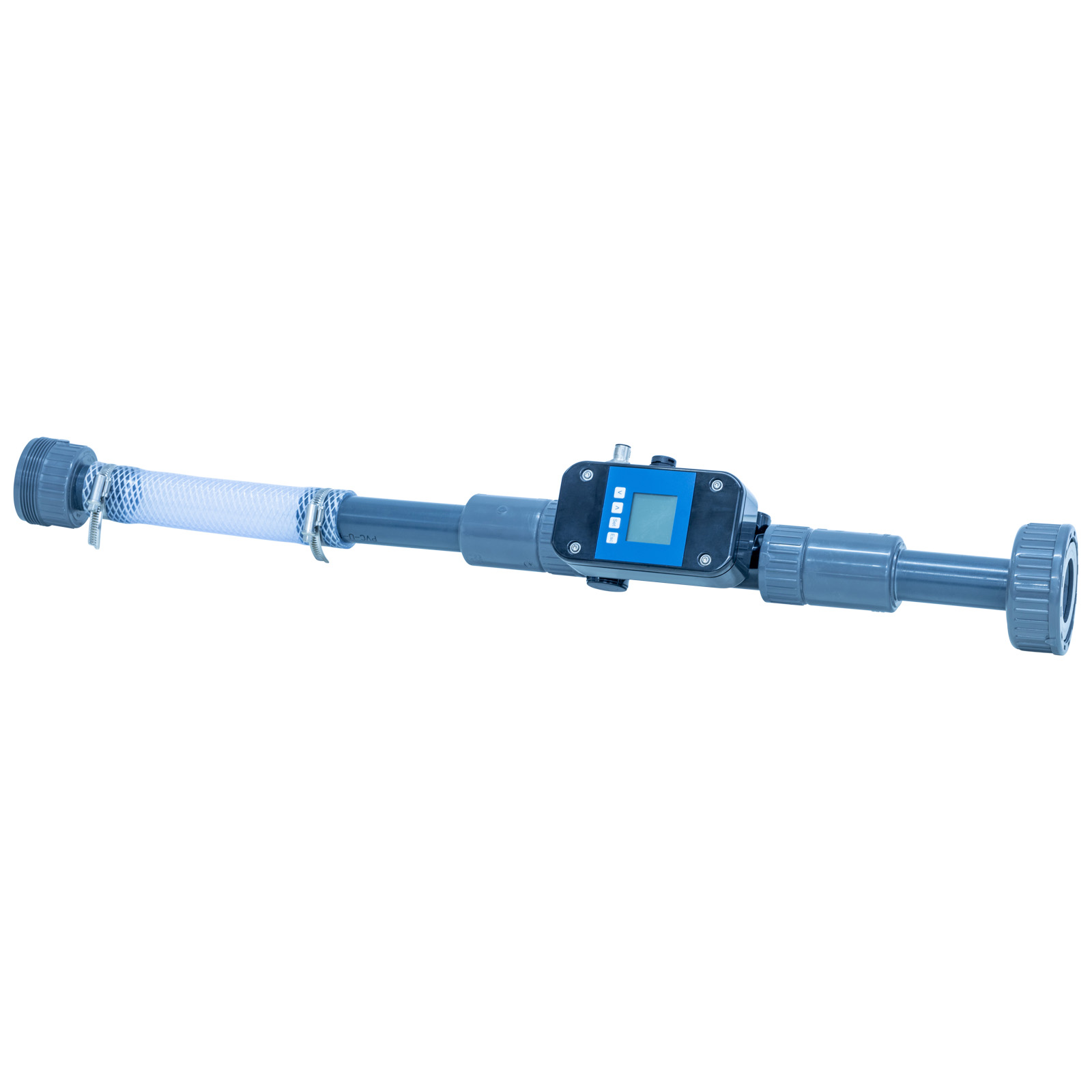
C9-MKII-2: Ultrasonic Flowmeter
The C9-MKII-2 Ultrasonic Flowmeter utilises ultrasound to measure the velocity of a liquid and is used in a variety of liquid applications.
Ultrasonic flowmeters are ideal for water and other liquids. They are a non-intrusive means of measuring liquid flow.
Supplied with direct datalogging via the supplied armBUS™ software (requires AIU-4 as an essential accessory)

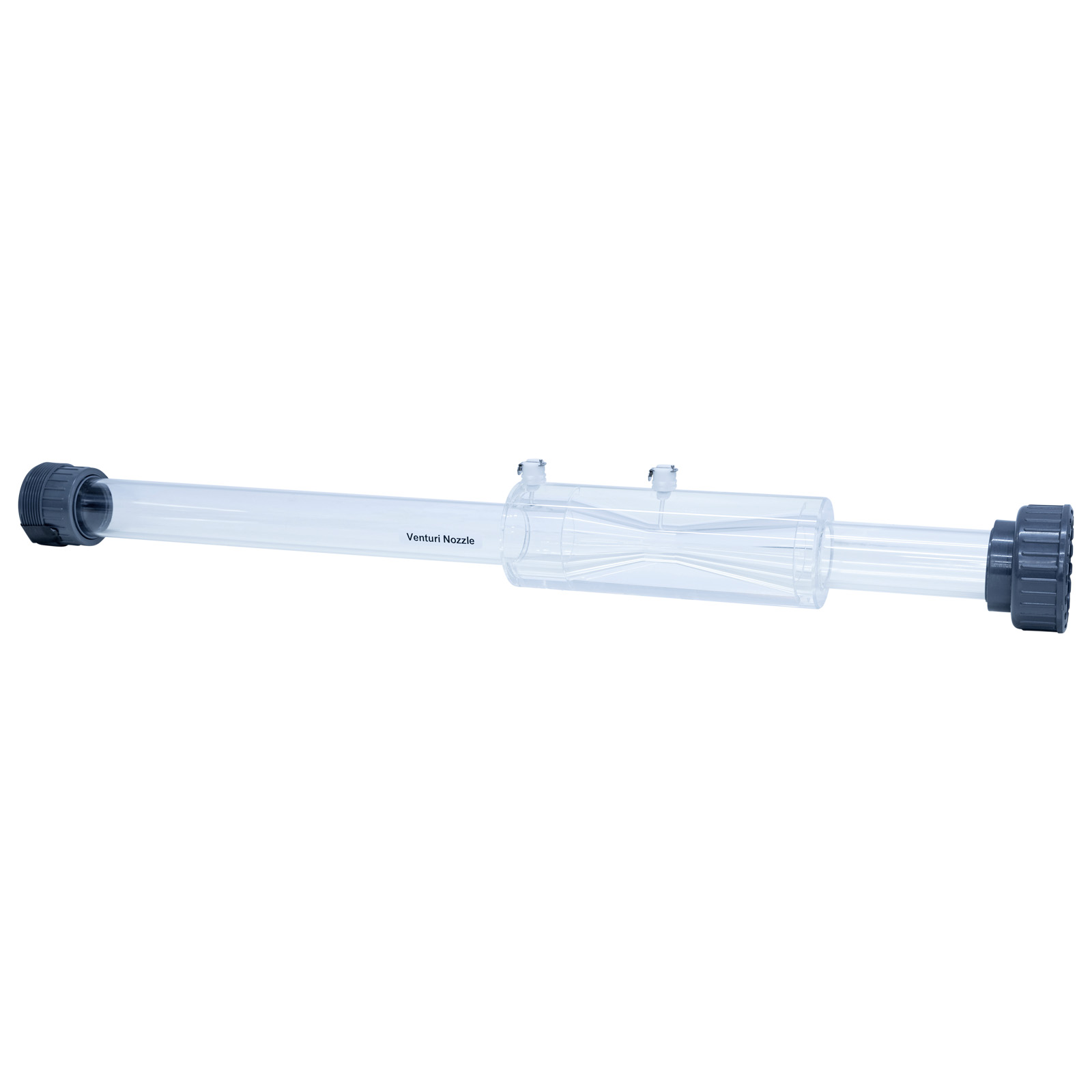
C9-MKII-3: Venturi Nozzle
The C9-MKII-3 Venturi Nozzle is a simple flow meter which requires no moving parts. The venturi meter is a device that demonstrates the Bernoulli equation to give a measurable pressure difference between the inlet (P1) and the throat (P2) that is related to the velocity of the liquid and hence the flowrate.
The venturi meter also has a divergent section downstream of the throat that allows the liquid to decelerate in a more efficient manner such that the original static pressure at P3 can be recovered.
Data is manually entered into the supplied armBUS™ software

C9-MKII-4: Pitot Tube
The C9-MKII-4 Pitot Tube is a differential pressure measuring device. The pitot tube installed in the flow stream measures the direct pressure at the contact pitot tube hole and a second measurement is required, being of static pressure.
The difference between the two measurements gives a value for dynamic pressure. While accuracy and rangeability are relatively low, pitot tubes are simple, reliable, inexpensive and suited for a variety of environmental conditions, including extremely high temperatures and a wide range of pressures. Data is manually entered into the supplied armBUS™ software.

C9-MKII-5: Orifice Plate Flowmeter
The C9-MKII-5 Orifice Plate Flowmeter is a simple device often used to determine flowrate from measuring the pressure drop across the orifice. It is a cheaper device to install than a venturi.
The main difference is that there is little pressure recovery downstream of the throat because of the abrupt opening back to the original pipe bore. Data is manually entered into the supplied armBUS™ software

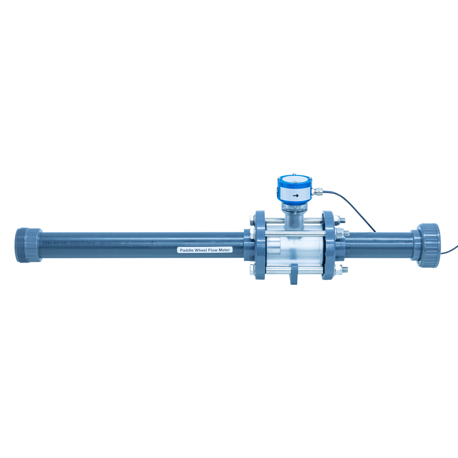
C9-MKII-6: Paddle Wheel Flowmeter
The C9-MKII-6 Paddle Wheel Flowmeter utilises the mechanical energy of liquids to rotate the paddle wheel through a flow stream and measure the liquid flow as it passes through. In paddle wheel flowmeters, the paddles are arranged around a central rotor and these paddles are then positioned in the flow. The pressure created by the paddles obstructing the flow result in rotational movement of the rotor. When the liquid moves faster, the paddle wheel spins proportionally faster so that the movement is proportional to the flow rate. This rotation can be detected, measured and, through various mechanisms or calculations provide an actual flow rate. Paddle movement is commonly detected magnetically but paddle wheel flowmeters can also be configured to detect the rotational speed optically or magnetically.
Supplied with direct datalogging via the supplied armBUS™ software (requires AIU-4 as an essential accessory)

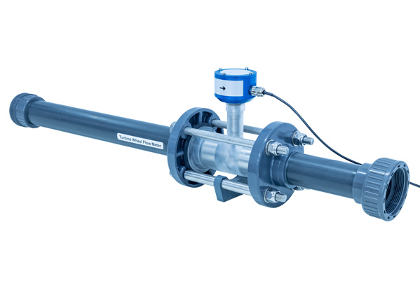
C9-MKII-7: Turbine Wheel Flowmeter
The C9-MKII-7 Turbine Wheel Flowmeter measures flow by using the mechanical energy of a liquid to rotate an axial turbine rotor that is located within the flow stream.
The rotations are measured and used to calculate a proportional measurement relative to the flowrate. The liquid flow causes the turbine rotor to rotate at an angular velocity proportional to the liquid flow rate. The angular velocity of the spinning turbine rotor results in the generation of an electrical signal. This electrical signal, for example a pulsed signal or AC sine wave, is related directly to the total flow based upon calibration data for the specific flow meter being used and thus the flow rate. The turbine rotor is the only moving part within the flow meter assembly. Supplied with direct datalogging via the supplied armBUS™ software (requires AIU-4 as an essential accessory)
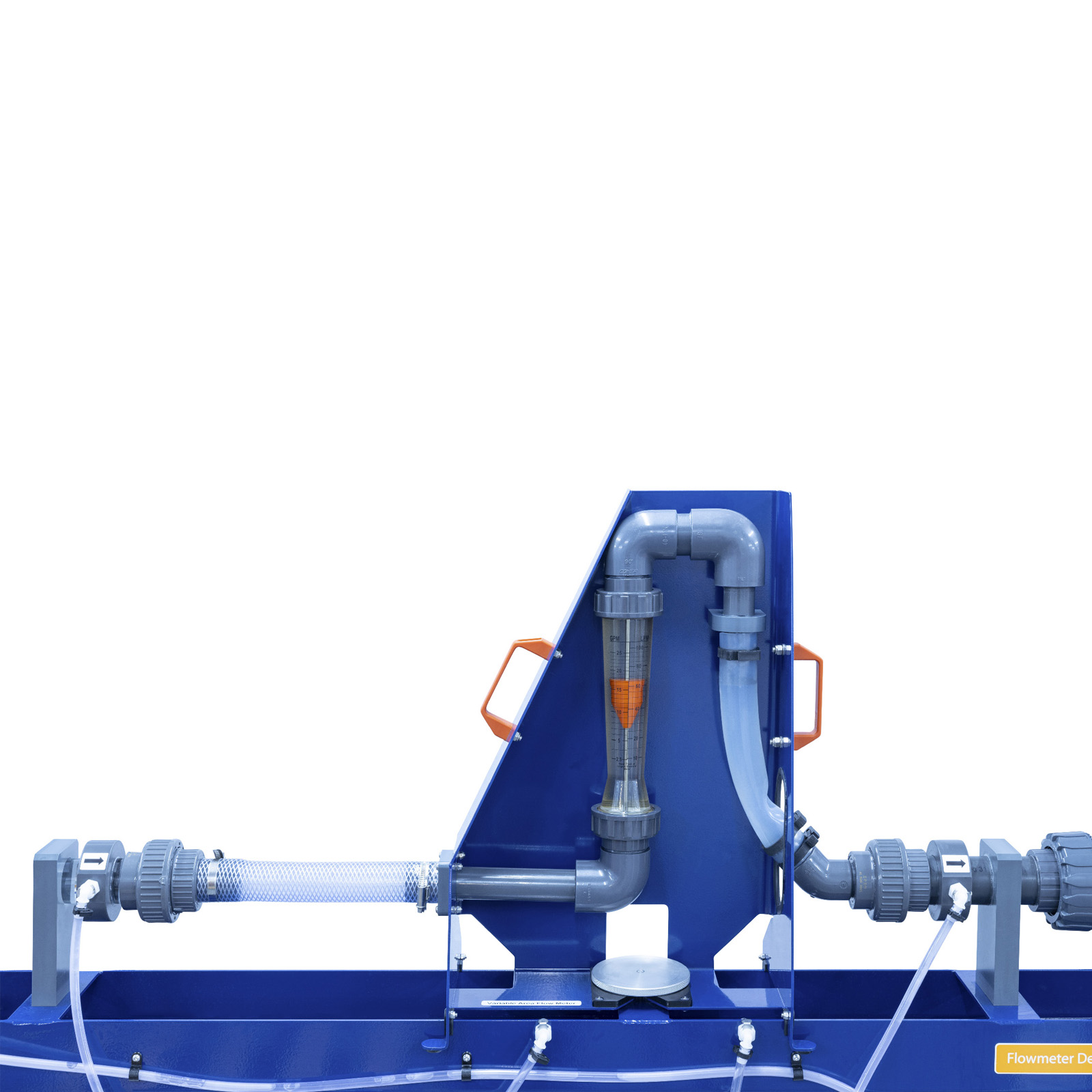
C9-MKII-8: Variable Area Flowmeter
The C9-MKII-8 Variable Area Flowmeter consists of a tapered transparent tube with a scale and within an internal, self-centring float that moves with changing liquid flow rate. As the flow increases this float moves to a higher position until its resistance to the liquid flow is balanced by the floats buoyed weight in the liquid, a value which is constant and independent of the flowrate.
The variable area flowmeter operates at a constant pressure delta, hence why the area between the tube and float changes with flow rate, e.g. the area between the float and tube increases as the flow rate increase through the meter to preserve the constant pressure delta. Data is manually entered into the supplied armBUS™ software

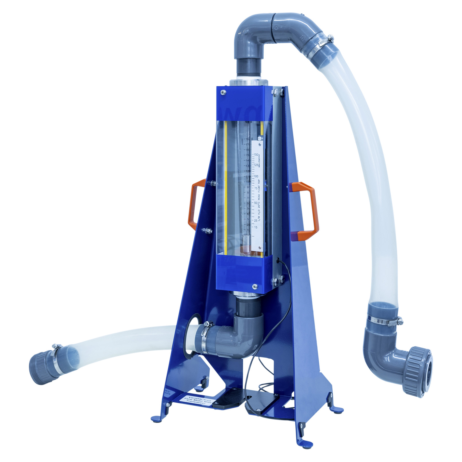
C9-MKII-9: Variable Area Flowmeter with Transducer
The C9-MKII-9 Variable Area Flowmeter with Transducer has a transducer system that can relay a digital or analogue signal in conjunction with the visual variable area float. This gives the flowmeter the obvious advantage of a local and remote determination of flow rates.
This particular variable area flowmeter incorporates a sensor providing a 4-20mA signal output which can be interrogated remotely. The principle of the variable area component of this flowmeter is the same as that of the C9-MKII-8.
Supplied with direct datalogging via the supplied armBUS™ software (requires AIU-4 as an essential accessory)
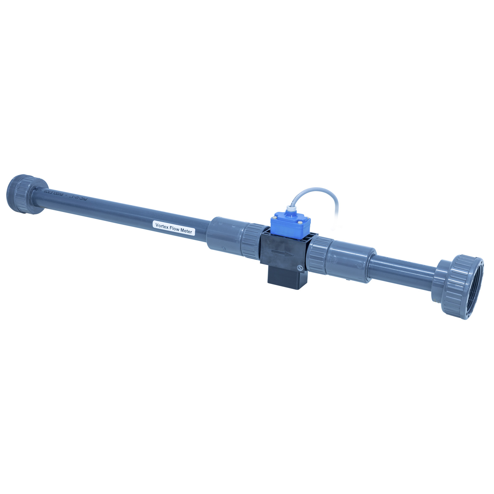
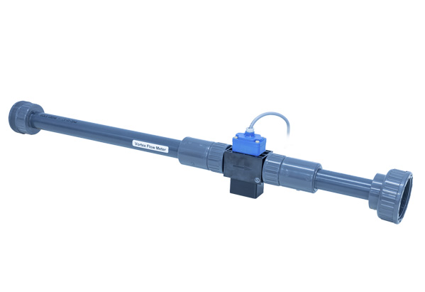
C9-MKII-10: Vortex Flowmeter
The C9-MKII-10 Vortex Flowmeter is essentially a frequency meters, since they measure the frequency of vortices generated by a bluff body or shedder bar. Vortices will only occur from a certain velocity (Reynolds number) onwards, consequently vortex meters will have an elevated zero referred to as the “cut-off” point. Before the velocity becomes nil, the meter output will be cut to zero. Vortex flowmeters make use of a principle called the von Kármán effect. According to this principle the flow alternately generates vortices each side when passing by a bluff body. A bluff body is that which has a broad, flat front. In a vortex meter, the bluff body is a piece of material with a broad, flat front that extends downstream.
Supplied with direct datalogging via the supplied armBUS™ software (requires AIU-4 as an essential accessory)
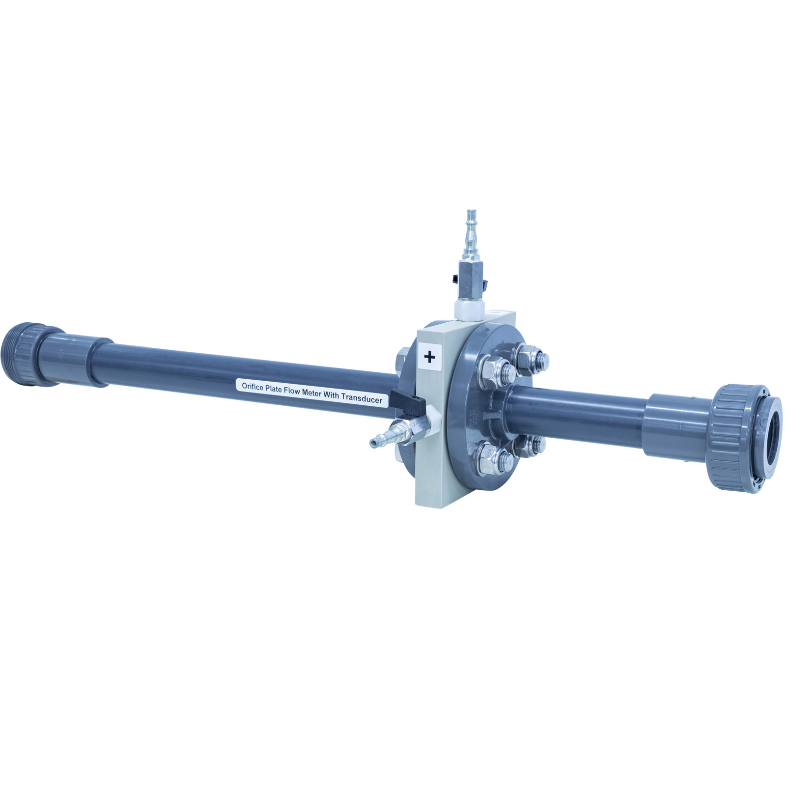
C9-MKII-11: Orifice Plate Flowmeter with Transducer
The C9-MKII-11 Orifice Plate Flowmeter uses the same for the basic principles as the C9-MKII-5 for the use of an orifice plate to determine flowrate. In this flowmeter rather than use a separate manometer to determine the differential pressure the differential pressure is determined by use of a transducer, normally of a variable capacitor, (diaphragm type). Supplied with direct datalogging via the supplied armBUS™ software (requires AIU-4 as an essential accessory)

C9-MKII-12: Bypass Flowmeter
The C9-MKII-12 Bypass Flow Meter consists primarily of an orifice plate as the sensor and a float as the display element. A differential pressure is produced across the orifice plate which is fitted in the main liquid stream between two flanges. In the bypass element the differential pressure produces a volume flow in a variable area meter. The height of the float indicates the flow rate and the flow is read at the position of the floats’ widest diameter. Data is manually entered into the supplied armBUS™ software

C9-MKII-13: Baffle Plate Flowmeter
The C9-MKII-13 Baffle Plate Flowmeter consists of a baffle plate with a balance beam that operates using a deflection method. The baffle plate causes a back pressure in the liquid media which causes the balance beam to be deflected. The movement of the balance beam is translated to the indicator mechanism, typically using a bellows. Through the indicator mechanism the movement is translated to a pointer where the flow can be read visually or converted to a digital or analogue electrical signal. Typically the mechanism includes and eddy-current brake to smooth the reading by dampening any turbulence and sudden flow changes. Supplied with direct datalogging via the supplied armBUS™ software (requires AIU-4 as an essential accessory)

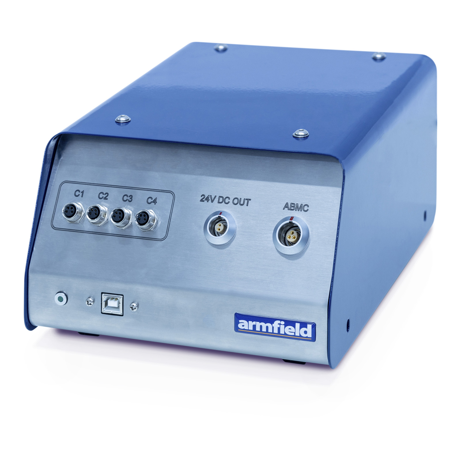
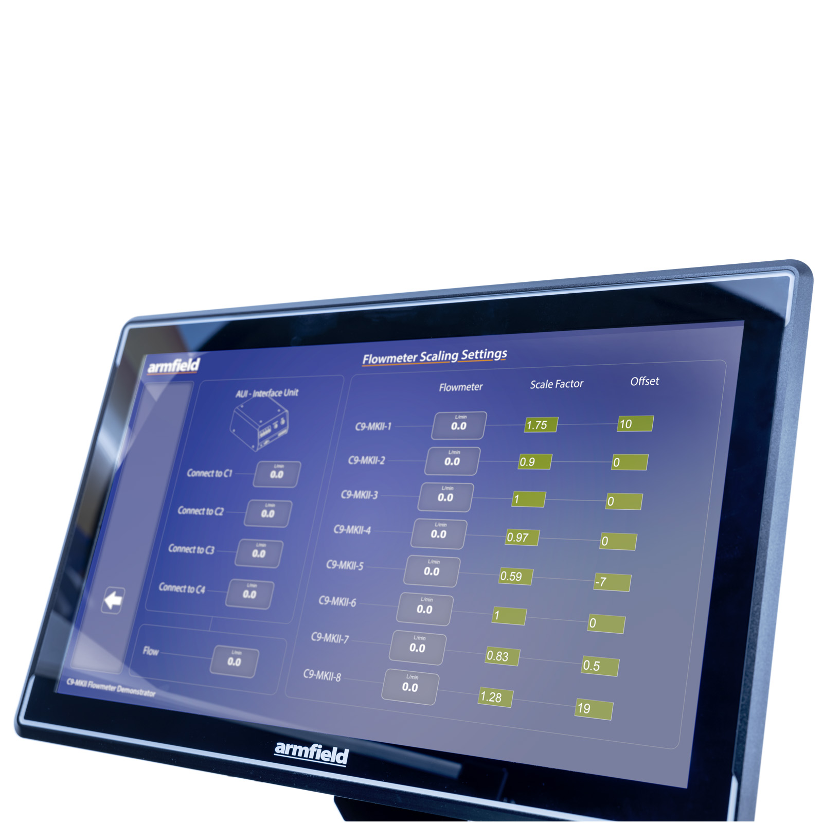
AIU – Armfield Interface Unit
The AIU4 Interface Console links the flowmeters with electronic outputs to the laptop or PC. The console interprets the signals received into the correct output format for the armBUS™ software.
The console has a 24vDC power supply to reduce the risk of high voltage incidents with contact with water.

The armBus™ user interface is an intuitive application for the collection of data for the complete set of flowmeters available.
Features
- Full Graphical User Interface (GUI) for each Flowmeter with display screens tailored for each exercise
- The software can be used to either log user inputted data or collect electronically captured data. The user logged data will be of differential pressure and flow values
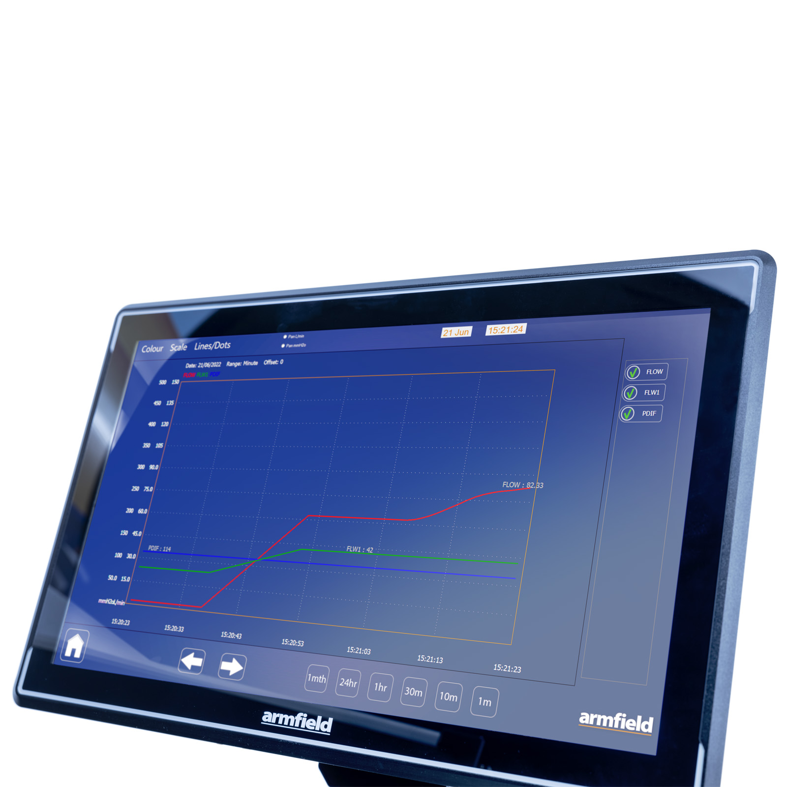
- Data is collated, and calculations are displayed in a data-log, a tabulation function provided with the armBUS™ software. The data is in tabulated format and can be saved and accessed through a .csv file compatible with software such as Microsoft Excel
- The data from the Flowmeters is plotted and displayed in a user configurable graphing function of the software
- F1-10: Hydraulics Bench
- Electrical supply: 110/120V, 60Hz or 220/240V, 50Hz
- Water supply: Initial fill with clean water
- The user must have a PC with a USB port, running Windows 7 or above
PACKED AND CRATED SHIPPING SPECIFICATIONS
Volume: 3m³
Gross Weight: 400kg
Length: 0.8m
Width: 2.5m assembled, 3.35m with F1-10 Hydraulics Bench
Height: 1.50m
- C9-MKII Flowmeter Demonstator
- C9-MKII-1 Electromagnetic Flowmeter (requires AIU-4 as an essential accessory)
- C9-MKII-2 Ultrasonic Flowmeter (requires AIU-4 as an essential accessory)
- C9-MKII-3 Venturi Nozzle
- C9-MKII-4 Pitot Tube
- C9-MKII-5 Orifice Plate Flowmeter
- C9-MKII-6 Paddle Wheel Flowmeter (requires AIU-4 as an essential accessory)
- C9-MKII-7 Turbine Wheel Flowmeter (requires AIU-4 as an essential accessory)
- C9-MKII-8 Variable Area Flowmeter
- C9-MKII-9 Variable Area Flowmeter with Transducer (requires AIU4 as an essential accessory)
- C9-MKII-10 Vortex Flowmeter (requires AIU-4 as an essential accessory)
- C9-MKII-11 Orifice Plate Flowmeter with Transducer (requires AIU-4 as an essential accessory)
- C9-MKII-12 Bypass Flowmeter
- C9-MKII-13 Baffle Plate Flowmeter (requires AIU-4 as an essential accessory)
- AIU-4 Four I/O Armfield interface unit