


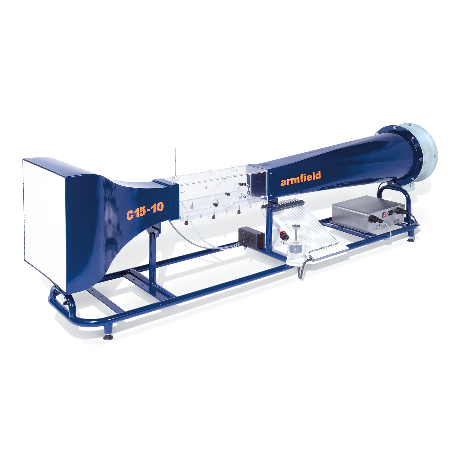


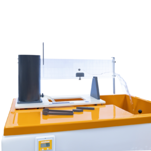
C15 – Computer Controlled Subsonic Wind Tunnel
A compact benchtop wind tunnel, with visible working section.
A wide range of accessories and instrumentation options are available, allowing a comprehensive study of Subsonic Aerodynamics and Fluid Mechanics.
Description
The C15-10 is a computer controlled compact wind tunnel designed for benchtop operation. Air is drawn through the working section by a variable speed fan at the discharge end of the tunnel providing up to 34m/s air velocity.
A honeycomb flow straightener is incorporated at the inlet, and a 9:4:1 contraction ratio which ensures an uniform airflow through the working section.
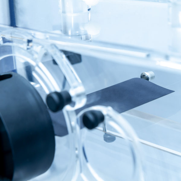
The working section is fabricated from clear acrylic to provide optimum visibility of the models, and appropriate model connection points are included in the side wall and roof of the working section to provide ease of use.
The wind tunnel is supplied as standard with an in-depth software interface providing control of the fan speed and additionally display important parameters such as static pressure and air velocity.
The Armfield C15-10 can be optionally supplied with two variants of manometry banks, a 13 tube water manometer used to simultaneously display differential pressure or a sixteen channel electronic manometer allowing direct integration into the supplied software.
The wind tunnel can be supplied with a range of optional accessories including drag bodies, lift bodies, pressure distribution, boundary layers studies and measuring instruments.
The optional models are mounted through a circular hatch using quick release clamps (120mm diameter). The placement of the optional models has been designed to minimise the disturbance to air flow and reduction in flow rate, whilst incorporating an angular scale allowing the model to be manually rotated to known angles.
The working section incorporates an innovative technique for flow visualisation around any of the optional models avoiding the need for either smoke or dry ice. A lightweight twine follows the flow contour around the model and shows if and where boundary layer separation (breakaway) occurs.


Technical Specifications
- Motor Rating: 0.51 kW 3 phase, 220VΔ (maximum speed 50 Hz through inverter)
- Working Section: 150mm x 150mm x 455mm
- Air Velocity: variable 0 to 34m/s
- Profiled Inlet: 9:4:1 (nominal) Contraction ratio
- Flow Visualization: Lightweight twine
Features & Benefits

- To convert a head measurement using a manometer to an equivalent pressure reading
- To demonstrate the use of a static pressure reading to determine tunnel air velocity
- To convert head and pressure readings to alternative engineering units
- To demonstrate the difference between Static pressure, Dynamic pressure and Total pressure and how Dynamic pressure can be used to determine air velocity
- To show how velocity varies in the test section because of the velocity profile
- To investigate the variation in Static Head resulting from a change in cross-sectional area
- To investigate the Bernoulli equation
- The visualisation of flow around a bluff body at different velocities
- The measurement of pressure distribution around a circular cylinder at different velocities
- Comparison of drag for shapes of equal equatorial diameter
- Visualisation of flow around different body shapes
- Measurement of the wake profile behind different shapes
- To investigate the pressure distribution around a symmetrical aerofoil at different angles
- To investigate the pressure distribution across the wake behind the wing
- To measure the depth of the boundary layer on smooth and rough flat plates
- To evaluate models or instruments of the student’s own design and/or manufacture
C15-11: Inclined Manometer Bank
The bank of 13 transparent tubes inclined at 30° to measure small pressure differences (0–160mm H2O).
It includes a water reservoir with screw operated displacer to allow rapid adjustment of the datum level in the manometer, and is fitted with quick release connectors for rapid connection to models and instruments.
Water is used as the manometer fluid for safety and convenience in use.

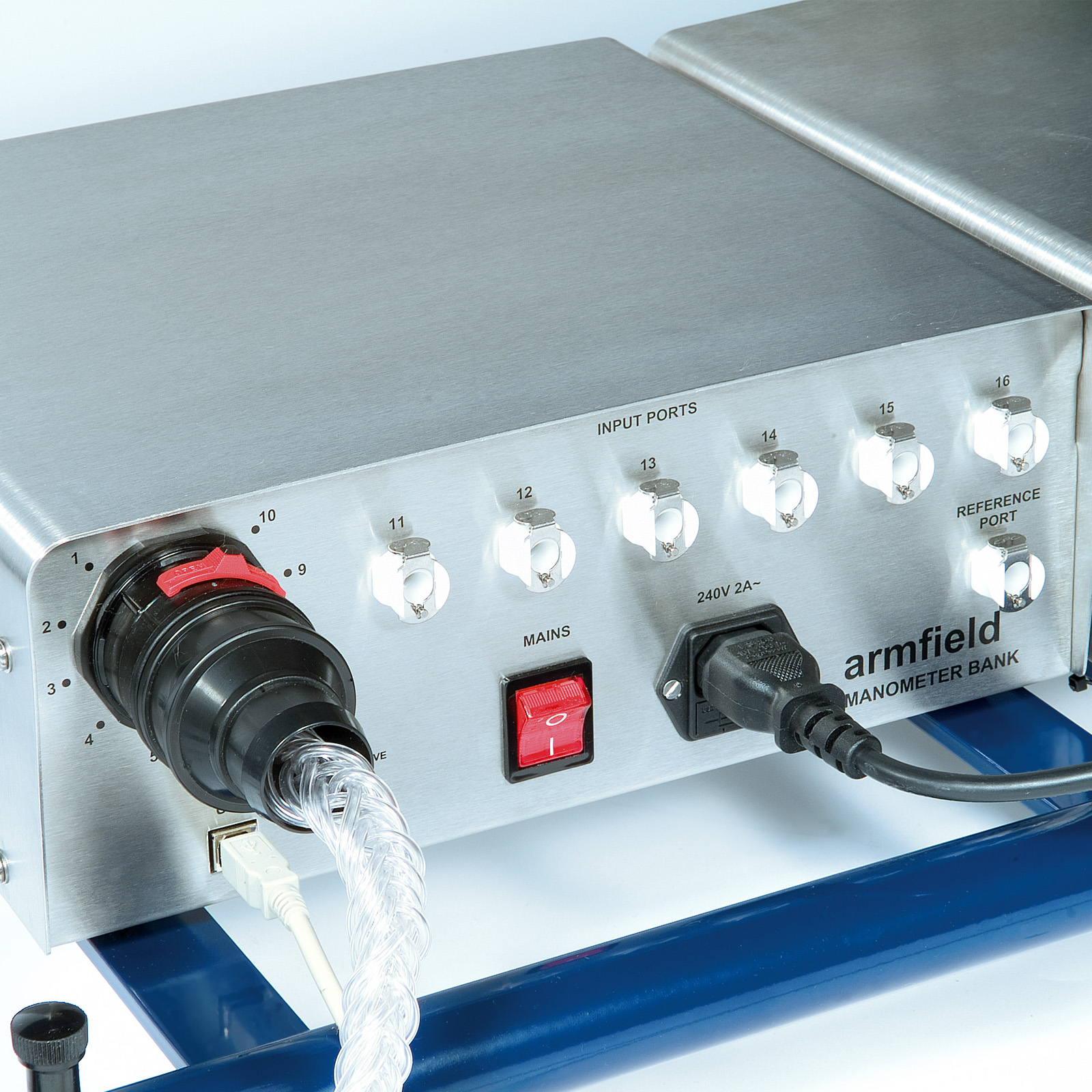
C15-12: Electronic Manometer Bank
An electronic console incorporating 16 differential pressure sensors, each with a range of 0-178mm H2O. (It connects to the control PC using a second USB port, and the readings are fully integrated with the wind tunnel control software.)
A common tapping allows all sensors to be referenced to atmospheric pressure. Quick release connectors allow for rapid connection to models and instruments.

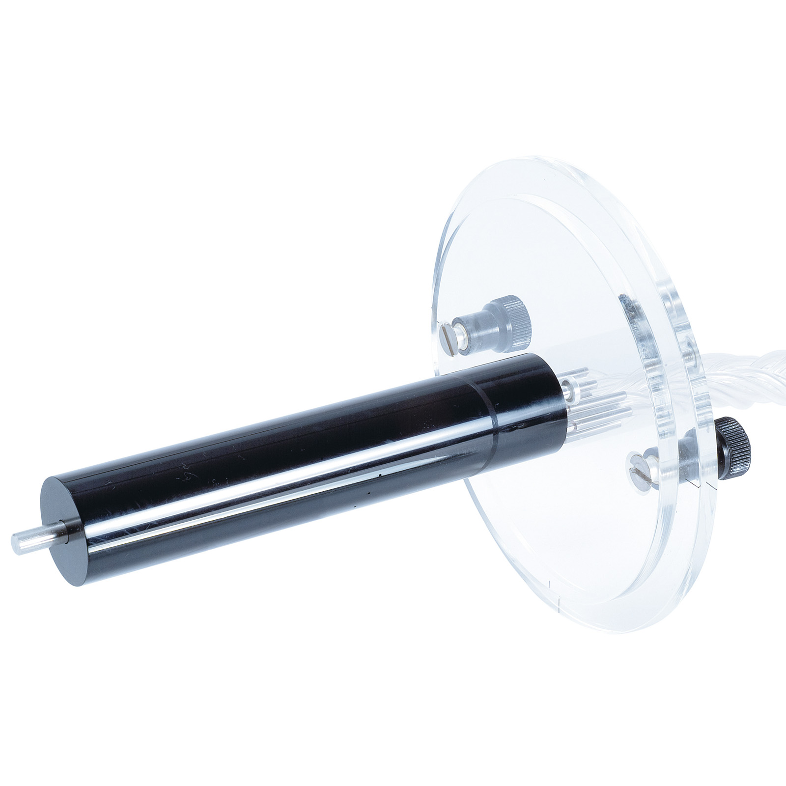
C15-13: Lift and Drag Balance (requires C15-20 or C15-22)
A 2-component, electronic balance used to measure the lift and drag on appropriate models. The lift and drag models connect to the balance using a simple fixing that ensures correct orientation of the model.
Electronic sensors are used to measure the lift and drag forces, the drag being measured directly, and the lift by a reduction in the model weight. The model being tested can also be rotated on the mounting and the angle of rotation measured electronically. The readings from the lift and drag sensors and the rotation sensor are displayed on the control software screen running on the PC, and are available for data logging. C15-13: Lift and drag Balance must be fitted to the C15 Wind Tunnel at time of order.

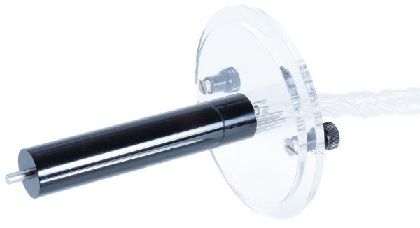
C15-14: Pitot Static Tube (requires C15-11 or C15-12)
A miniature Pitot Static Tube mounted in a support plug that can be located in the roof of the working section at three alternative positions, i.e. the start of the working section and upstream and downstream of the model mounting position.
The support plug incorporates an ‘O’ ring to retain the Pitot Tube where it is positioned and allows the tube to traverse over the full height of the working section to measure the velocity profile inside the working section of the tunnel.

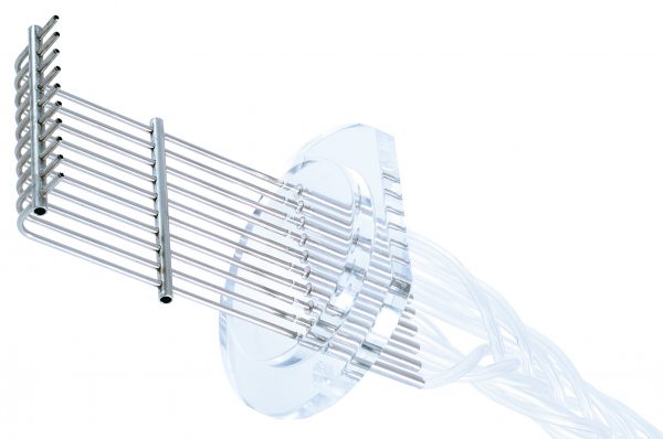
C15-15: Wake Survey Rake (requires C15-11 or C15-12)
The rake consists of 10 tubes positioned vertically in a row and pointing towards the airflow. The rake is mounted downstream of the model being used.
The tubes are mounted at a fixed pitch of 5mm but the assembly can be displaced 2.5mm allowing measurements at intervals of 2.5mm by interlacing two sets of readings.
The tubes are connected via flexible tubing to a multi-way quick release connector.
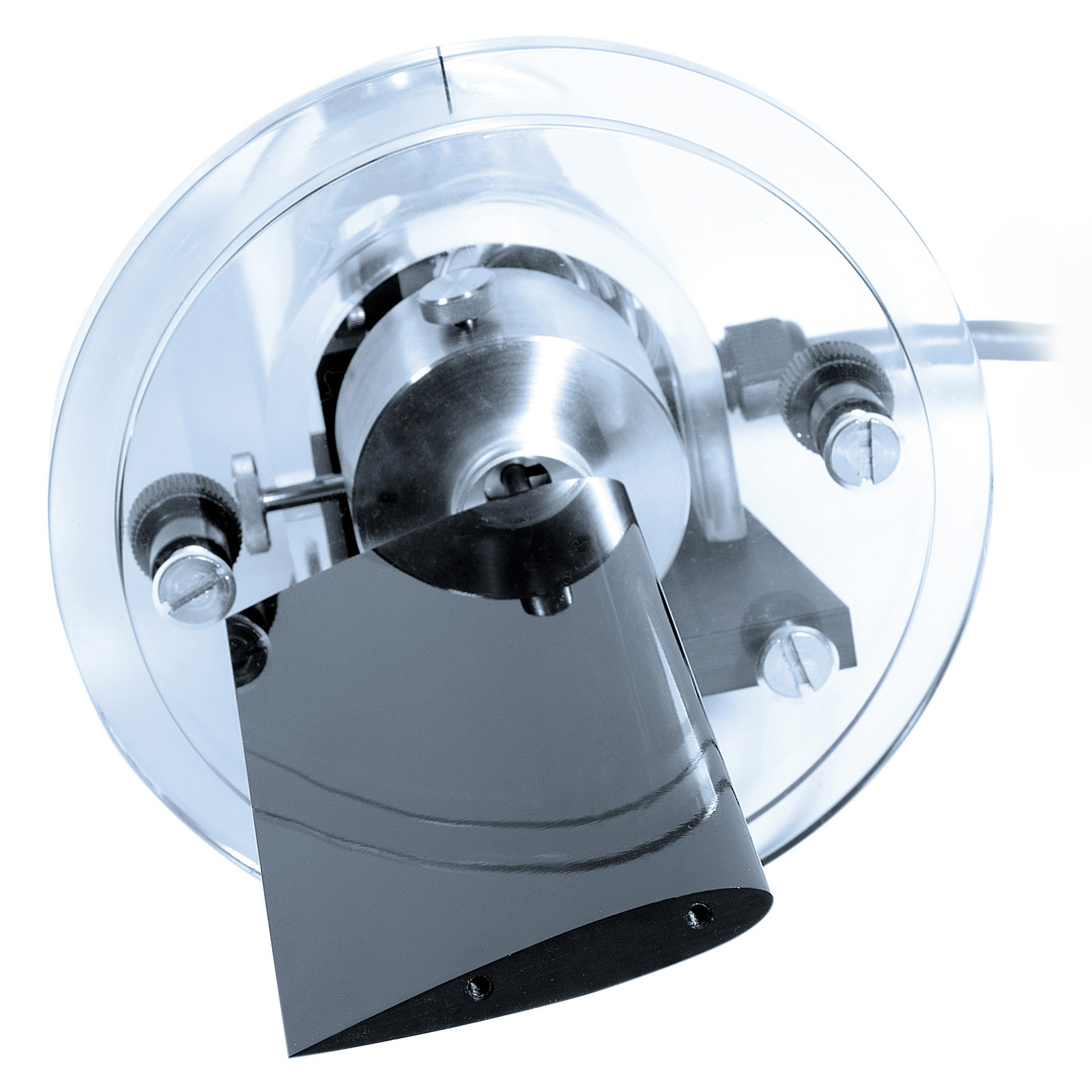
C15-16-Asoft: 3-Component Balance
A 3-component balance used to measure Lift, drag and moment forces on appropriate models. The models connect to the balance using a simple fixing that ensures correct orientation of the model. The system is designed to work with a series of Armfield models and also enables the user to manufacture and test their own 3D printed or fabricated wings to test and evaluate for project work. Integrated Electronic sensors are used to measure the lift, drag and moment forces. The model being tested can also be rotated on the mounting and the angle of rotation measured electronically. The readings from the lift, drag, moment sensors and the rotation sensor are displayed on the control
software screen running on the PC, and are available for data logging. C15-16-Asoft: 3-Component Balance must be fitted to the C15 Wind Tunnel at time of order.
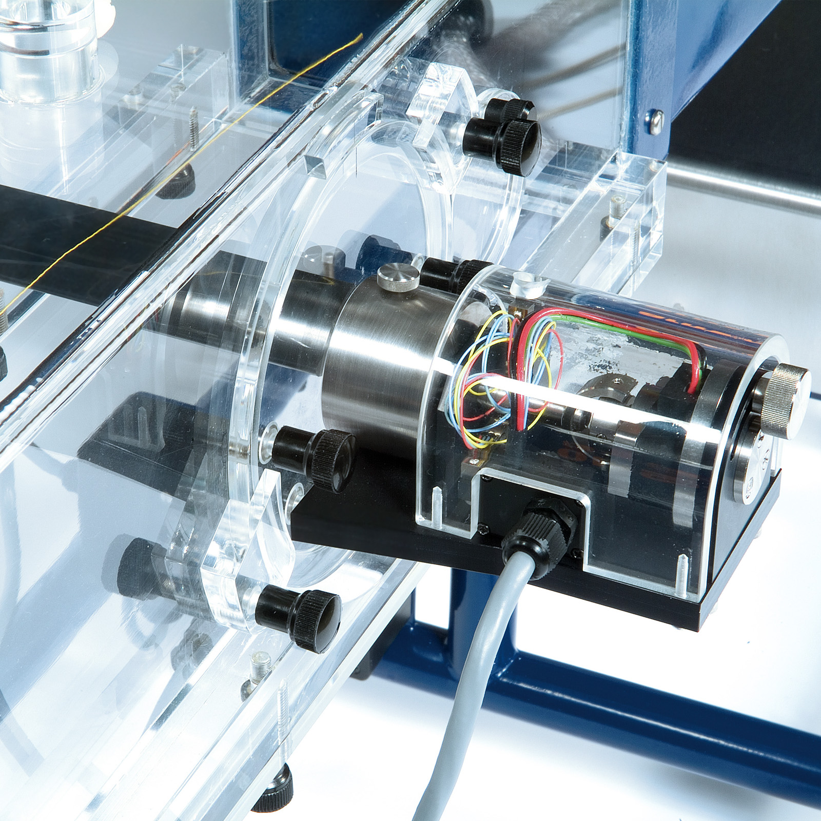
C15-17-Asoft: 3-Component Driven Balance (Requires C30-19)
A PC controlled Driven 3 component balance incorporates a closed loop stepper drive for precise driven rotation angles particularly beneficial for remote operation/ remote learning activities and repetitious test and development. C15-17-Asoft:3-Component Driven Balance must be fitted to the C15 Wind Tunnel at time of order. *requires essential accessory C15-19
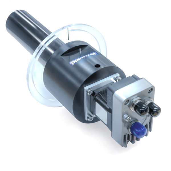
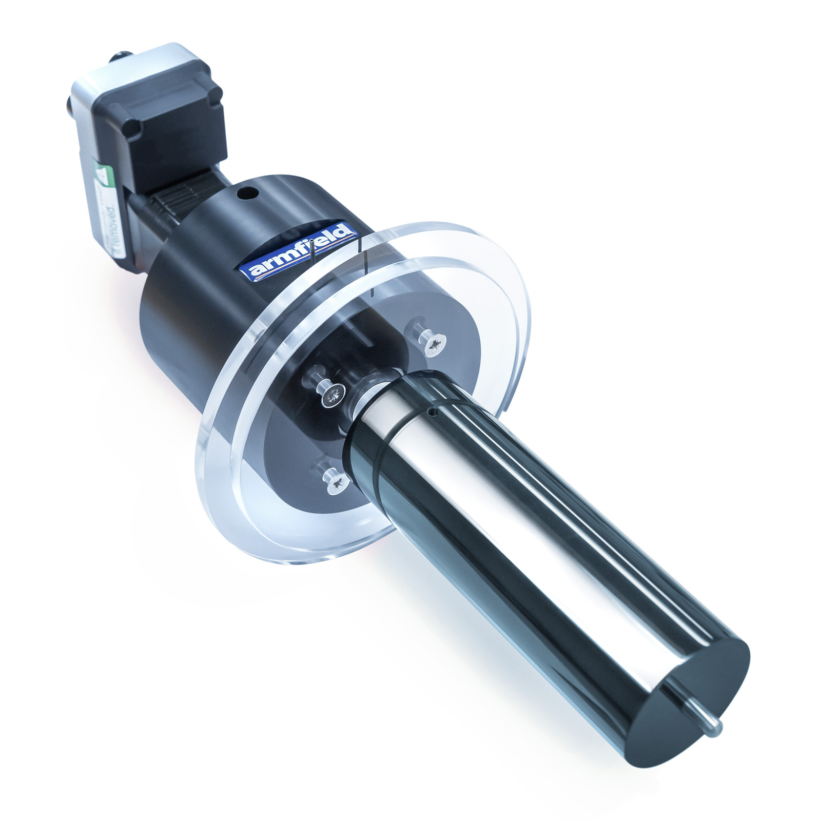
C15-18: Driven 360° Model Unit
A PC controlled Driven 3 component balance incorporates a closed loop stepper drive for precise driven rotation angles particularly beneficial for remote operation/ remote learning activities and repetitious test and development. C15-17-Asoft:3-Component Driven Balance must be fitted to the C15 Wind Tunnel at time of order. *requires essential accessory C15-19

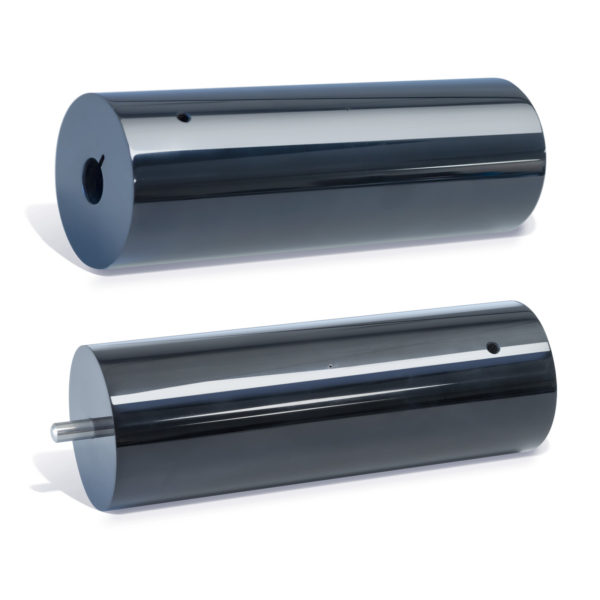
C15-18-01: Cylinder with pressure tapping for 360° drive
Cylinder with single pressure tapping to interface with the driven 360 degree model unit enabling the study of pressure acting on a cylinder at various velocities and angular positions.
C15-20: Lift & Drag Aerofoil (requires C15-13)
A plain symmetrical aerofoil to NACA 0015 profile, incorporating a mounting rod that allows it to be installed on the C15-13 Lift & Drag Balance, thus allowing the lift and drag to be measured with the aerofoil at different angles of attack.
The aerofoil has the same section as the C15-21 to allow direct comparison of lift characteristics with the pressure distribution.

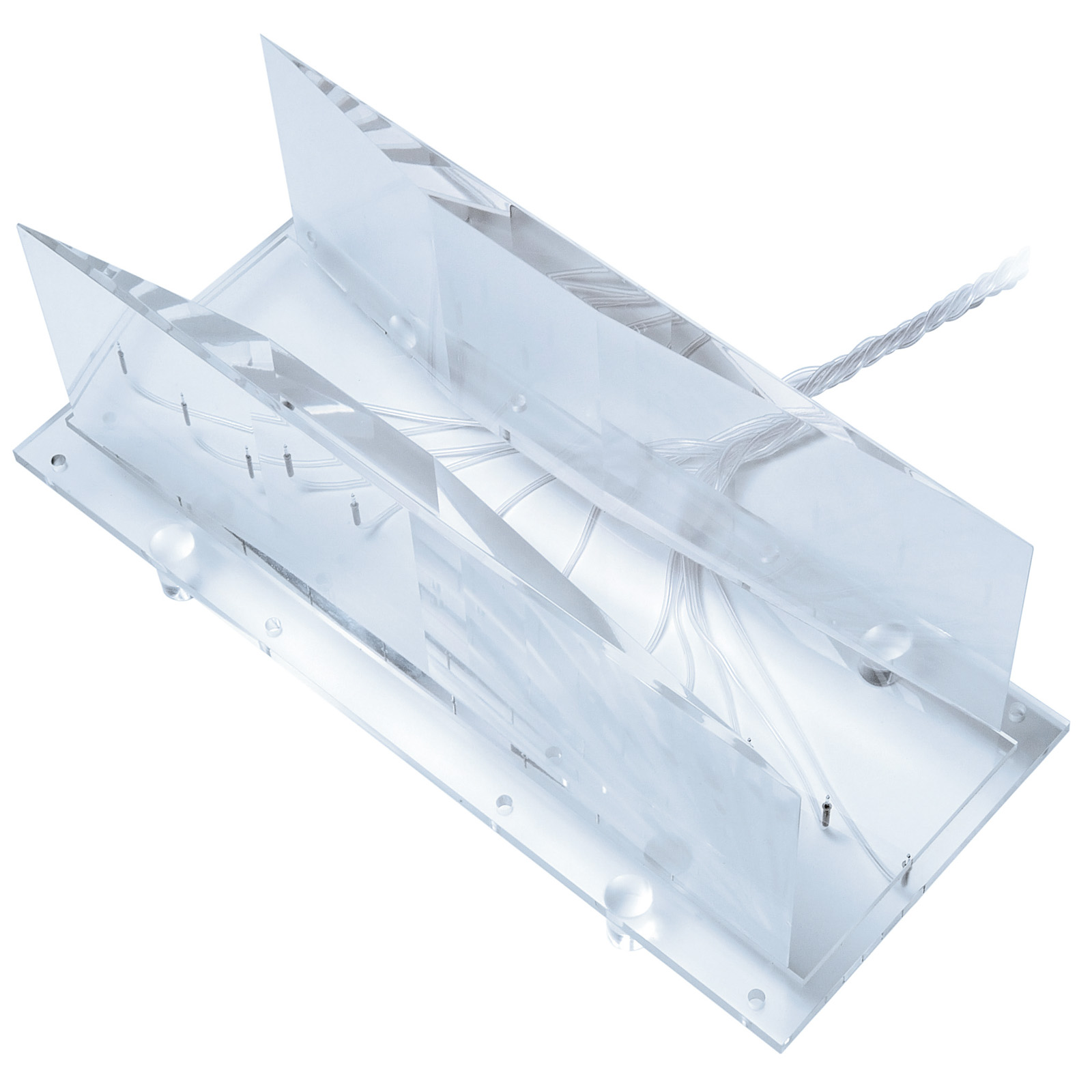
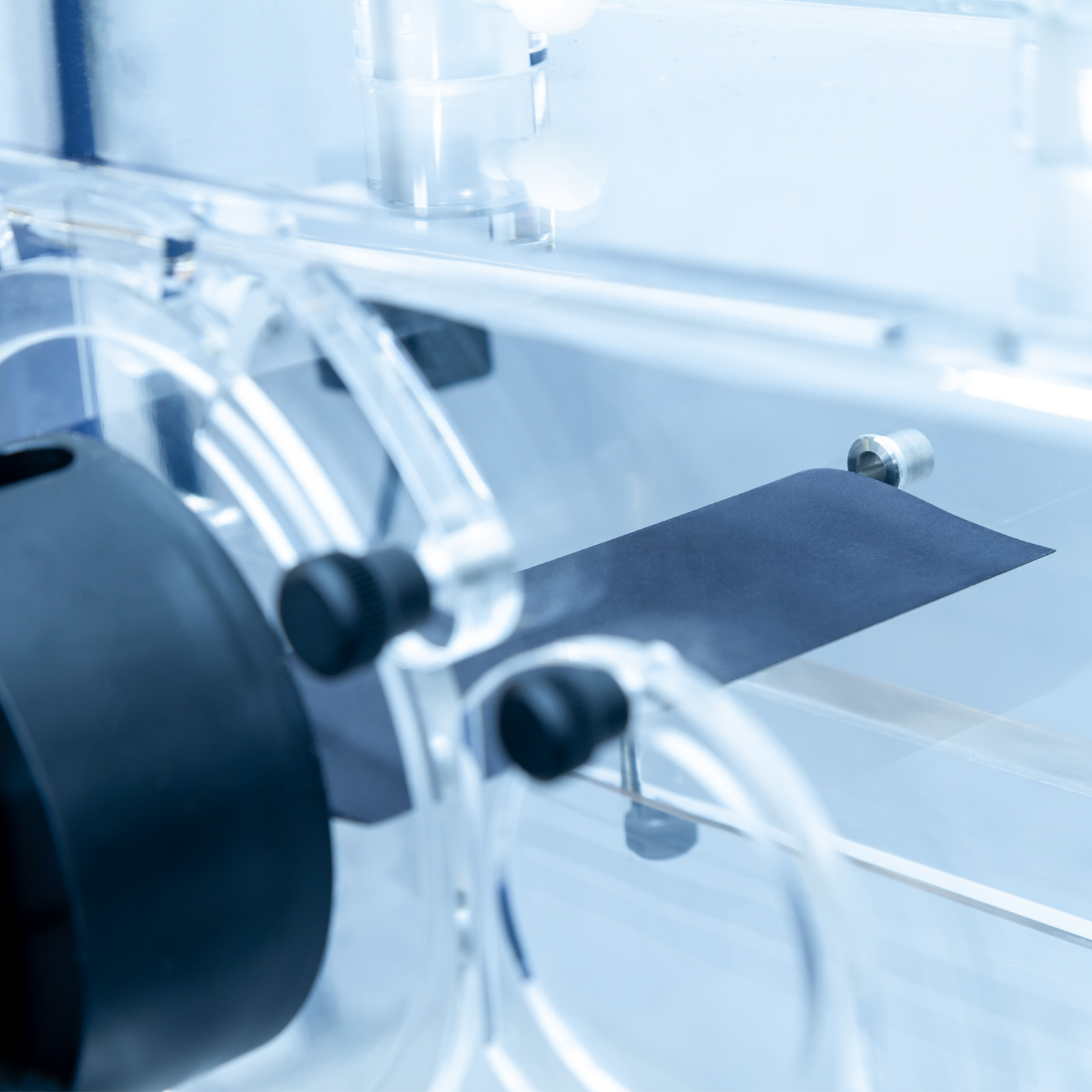
C15-21: Pressure Wing (requires C15-11 or C15-12)
A symmetrical aerofoil incorporating 10 tapping points distributed along the wing profile on one side, which allows the pressure distribution to be measured from the leading edge to the trailing edge.
The pressure distribution on the upper and lower surface can be obtained by inclining the aerofoil at positive and negative angles of attack. Machined to NACA 0015 profile, the aerofoil has the same section as the C15-20 to allow direct comparison of pressure distribution with the lift characteristics.
The tapping points are all flush with the surface of the aerofoil and connected via flexible tubing to a multi-way quick release connector.

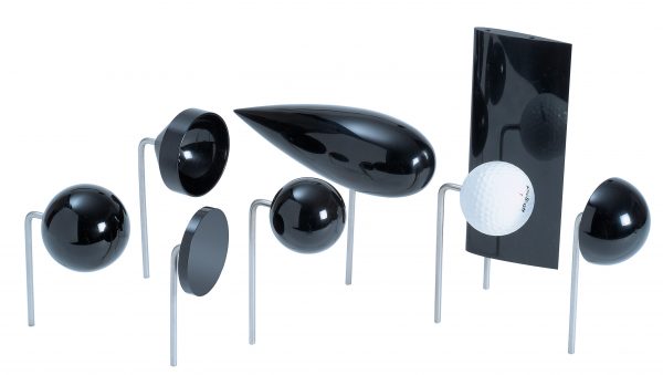
C15-22 Drag Models (requires C15-13)
Seven different models are provided for use with the C15-13 Lift and Drag Balance for investigations into the influence of shape on the drag forces.
Five models are supplied with a common equatorial diameter of 50mm, thus all presenting the same cross section to the airflow: Sphere – Hemisphere, convex to airflow – Hemisphere, concave to airflow – Circular disk – Streamlined shape.
Additionally a dimpled golf ball and plain sphere demonstrate the difference in drag force due to the dimples.
C15-23: Pressure Cylinder (requires C15-11 or C15-12)
A plain cylinder, 30mm diameter, incorporating 10 equi-spaced tapping points around half of the circumference that allow the pressure distribution around the cylinder to be measured.
The cylinder can be rotated through 180° to plot the pressure distribution over the whole circumference.
C15-24: Bernoulli Apparatus (requires C15-11 or C15-12)
A Venturi profile that is installed in the working section of the tunnel via the removable floor. The Venturi incorporates 11 pressure tappings in the floor, connected via flexible tubing to quick release connectors.
The Venturi occupies the full height of the working section and the width varies from 150mm (full width of the working section) at the inlet and outlet to 100mm at the throat. It is manufactured from clear acrylic for full visualisation.

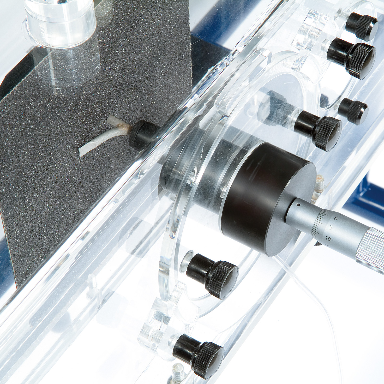
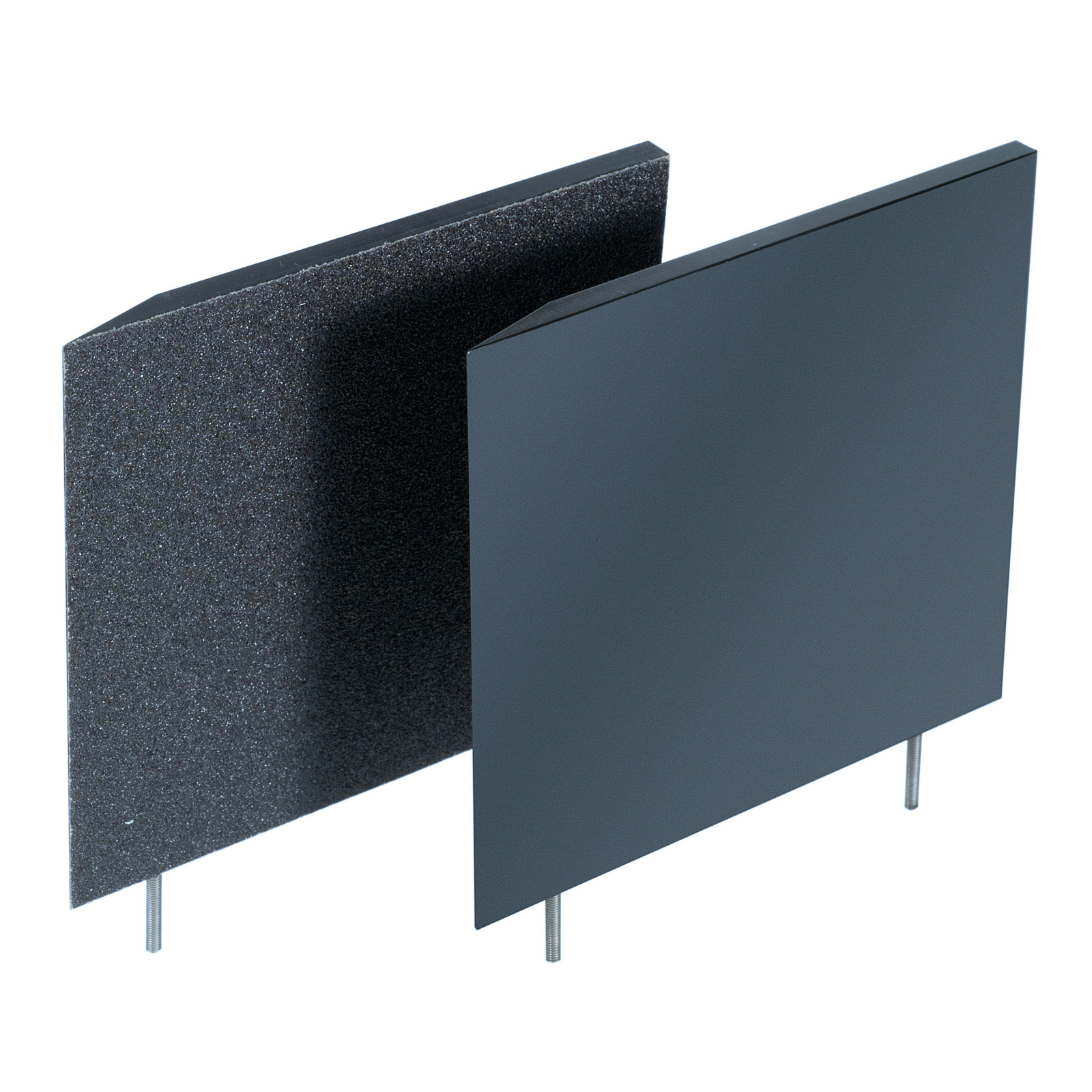
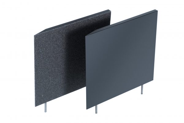
C15-25: Boundary Layer Plate (requires C15-11 or C15-12)
A flat plate, with a bevelled leading edge, that is mounted vertically in the working section via the removable floor. A flattened Pitot tube, mounted on a traversing micrometer, allows the air velocity to be measured at different distances from the surface of the plate.
A smooth plate and artificially roughened plate (above) are included to show the difference between laminar and turbulent boundary layers. The flexible tubing from the Pitot tube incorporates a quick release connector.

A selection of components that allow alternative models to be constructed by the user. Includes a floor panel, a circular hatch and a set of connectors with appropriate flexible tubing.
C15-10
- Motor Rating: 0.51 kW 3 phase, 220VΔ (maximum speed 50 Hz through inverter)
- Working Section: 150mm x 150mm x 455mm
- Air Velocity: variable 0 to 34m/s
- Profiled Inlet: 9:4:1 (nominal) Contraction ratio
- Flow Visualization: Lightweight twine
C15-11 Manometer
- Number of tubes:13 total/Tube length – 320mm
- Inclination: 30°
- Measuring range: 0 – 160mm H2O (0 – 6.3” H2O)
C15-12 Electronic Manometer
- Number of channels: 16
- Measuring range: 0 – 178mm H2O (0 – 7” H2O)
- Quick Release connectors: 7 x single / 1 x 10 way
C15-13 Lift and Drag Balance
- Range of lift measurement: 0 – 5.4 N (1.2 lb.f )
- Range of drag measurement: 0 – 5.4 N (1.2 lb.f )
- Rotation > +/- 45°
C15-14 Pitot Static Tube
- Diameter: 4mm
- Design: Prandtl
- Max angle of yaw: 5°
C15-15 Wake Survey Rake
- Number of Tubes: 10/Stainless Steel
- Pitch: Fixed 5mm
- Connector: 10-way Quick release
C15-20 Lift & Drag Aerofoil
- Aerofoil: NACA 0015
- Cord length: 61.5mm
- Thickness: 9.2mm
C15-21 Lift & Pressure Wing
- Aerofoil: NACA 0015
- Cord length: 61.5mm
- Thickness: 9.2mm
- Number of Tapping points: 10
- Connector: 10- way Quick release
C15-22 Drag Models
- Number of Models: 7
- Sphere: Equatorial diameter 50mm
- Hemisphere, convex to airflow: Equatorial diameter 50mm
- Hemisphere, concave to airflow: Equatorial diameter 50mm
- Circular disk: Equatorial diameter 50mm
- Streamlined shape: Equatorial diameter 50mm
- Dimpled golf ball: Diameter 43mm
- Plain Sphere: Diameter 43mm
C15-23 Pressure Cylinder
- Cylinder diameter: 30mm
- Number of Tapping points: 10
- Tapping spacing: 20°
- Angle of Rotation: 180°
- Connector: 10 – way Quick release
C15-24 Bernoulli Apparatus
- Throat width: 100mm
- Upstream/downstream width: 150mm
- Number of Tapping points: 11
- Material: Clear Acrylic
Electrical supply:
- C15-10-A: 220-240V/1/Phase, 50Hz, 10Amps
- C15-10-G: 220-240V/1/Phase, 60Hz, 10Amps
G version has optional 1.5kVA transformer available to accommodate 120V/1Ph/60Hz supply.
The user must have a PC with a USB port, running Windows 7 above. An additional USB port will be required when using the optional C15-12.
PACKED AND CRATED SHIPPING SPECIFICATIONS
Volume: 1.5m³
Gross Weight: 220Kg
Length: 2.250m
Width: 0.700m
Height: 0.460m
- C15-10-A Computer Controlled Wind Tunnel
- C15-10-G Computer Controlled Wind Tunnel
- C15-11 Inclined Manometer Bank
- C15-12 Electronic Manometer Bank
- C15-13 Lift and Drag Balance (requires C15-20 or C15-22)
- C15-14 Pitot Static Tube (requires C15-11 or C15-12)
- C15-15 Wake Survey Rake (requires C15-11 or C15-12)
- C15-16 Asoft 3-Component Balance
- C15-17 Asoft 3-Component Driven Balance – Armsoft
- C15-18 Driven 360 degree model unit
- C15-18-01 C15 pressure cylinder for 360 drive unit
- C15-19 Wind Tunnel Accessory PSU
- C15-20 Lift & Drag Aerofoil (requires C15-13)
- C15-21 Pressure Wing (requires C15-11 or C15-12)
- C15-22 Drag Models (requires C15-13)
- C15-23 Pressure Cylinder (requires C15-11 or C15-12)
- C15-24 Bernoulli Apparatus (requires C15-11 or C15-12)
- C15-25 Boundary Layer Plate (requires C15-11 or C15-12)
- C15-26 Project Kit
- C-Smoke-A or B Probe smoke generator