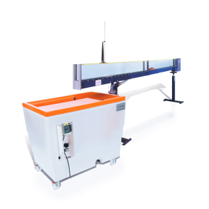
S8-MKII – Sediment Transport Demonstration Channel
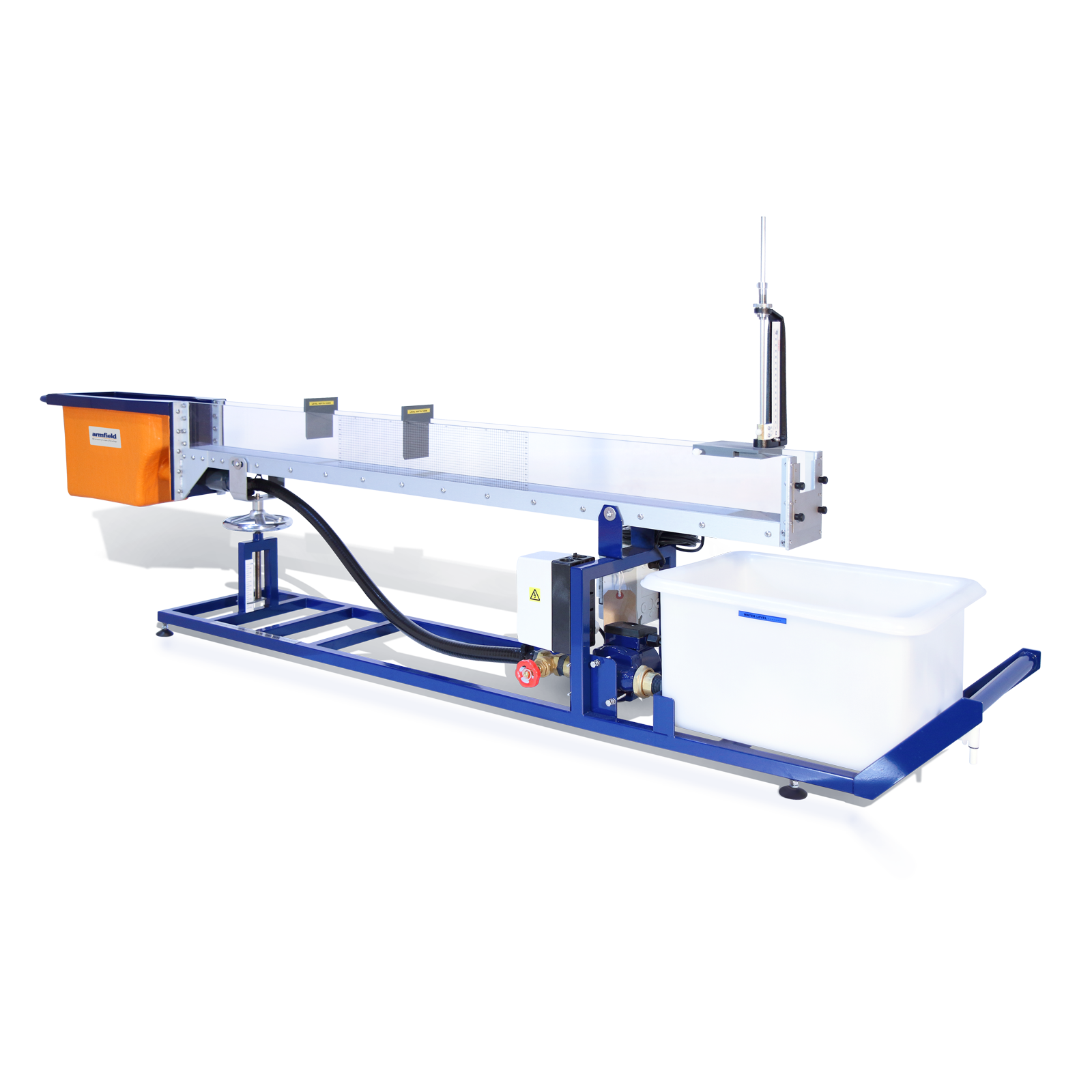
The Armfield Sediment Transport Demonstration Channel enables the demonstration of the full range of bedforms that arise in a mobile bed as the flow and/or slope are increased.
The channel can be used to perform most of the experiments and demonstrations usually undertaken in much larger laboratory flumes, but at a much lower cost and without the need for technician back up.
The flume can play a useful role in any course concerning the mechanics of open channel flow and sediment transport, including those in departments of civil engineering, geology and physical geography.
Description
The Armfield Sediment Transport Demonstration Channel enables the demonstration of the full range of bedforms that arise in a mobile bed as the flow and/or slope are increased.
The channel can be used to perform most of the experiments and demonstrations usually undertaken in much larger laboratory flumes, but at a much lower cost and without the need for technician back up.
The equipment is portable and therefore may be used in the classroom as well as in the laboratory. This demonstration flume can play a useful role in any course concerning the mechanics of open channel flow and sediment transport, including those in departments of civil engineering, geology and physical geography.
Sediment Transport Channel
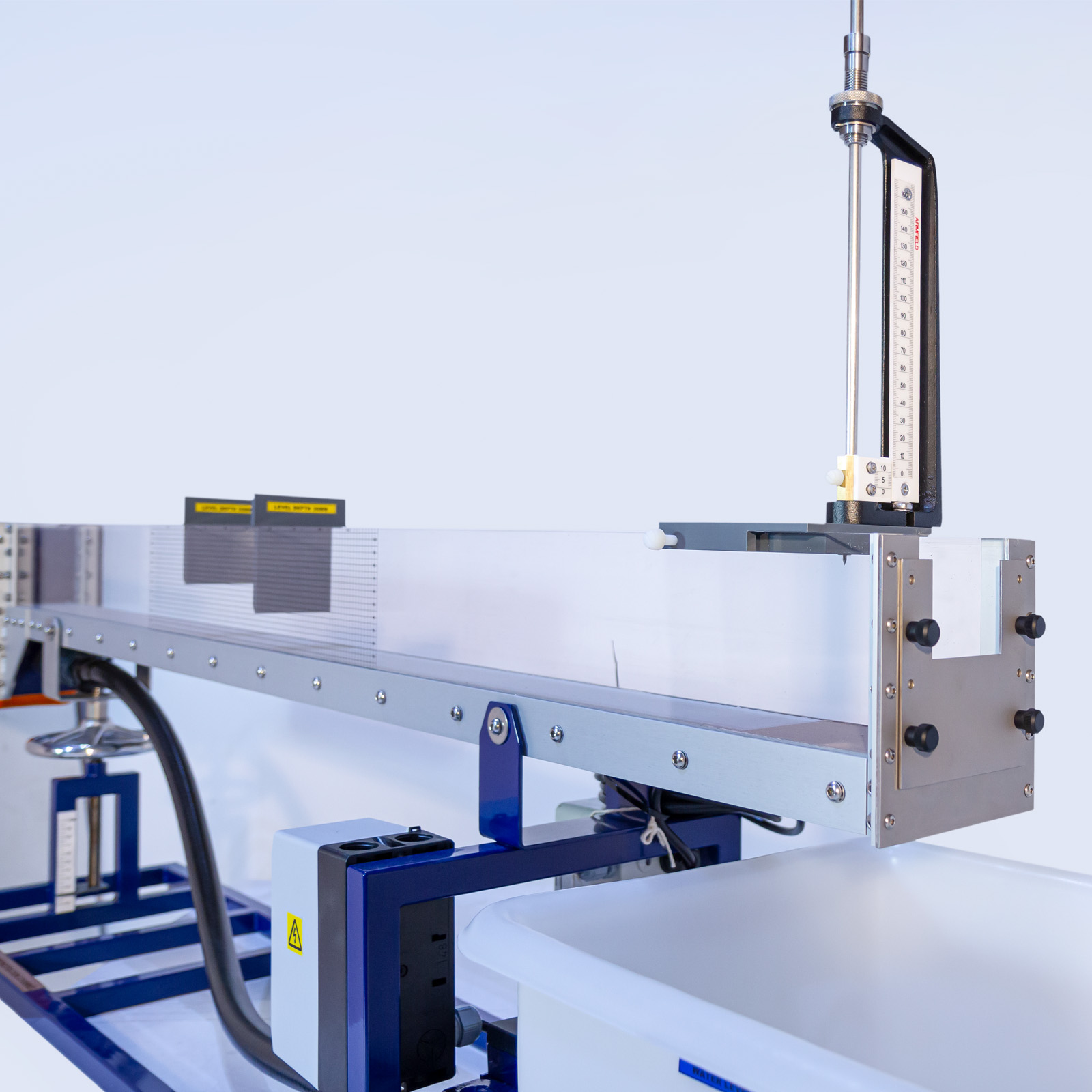
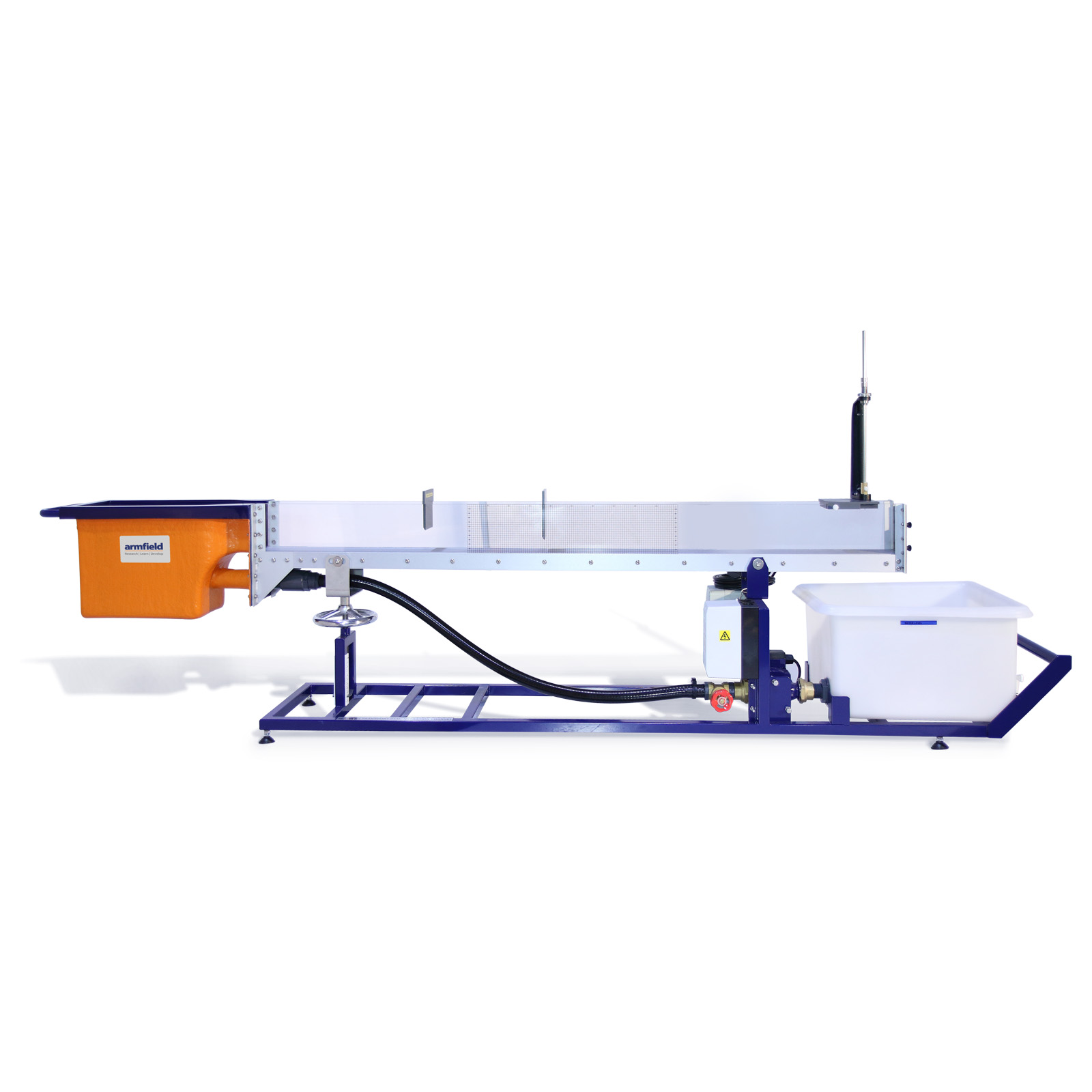
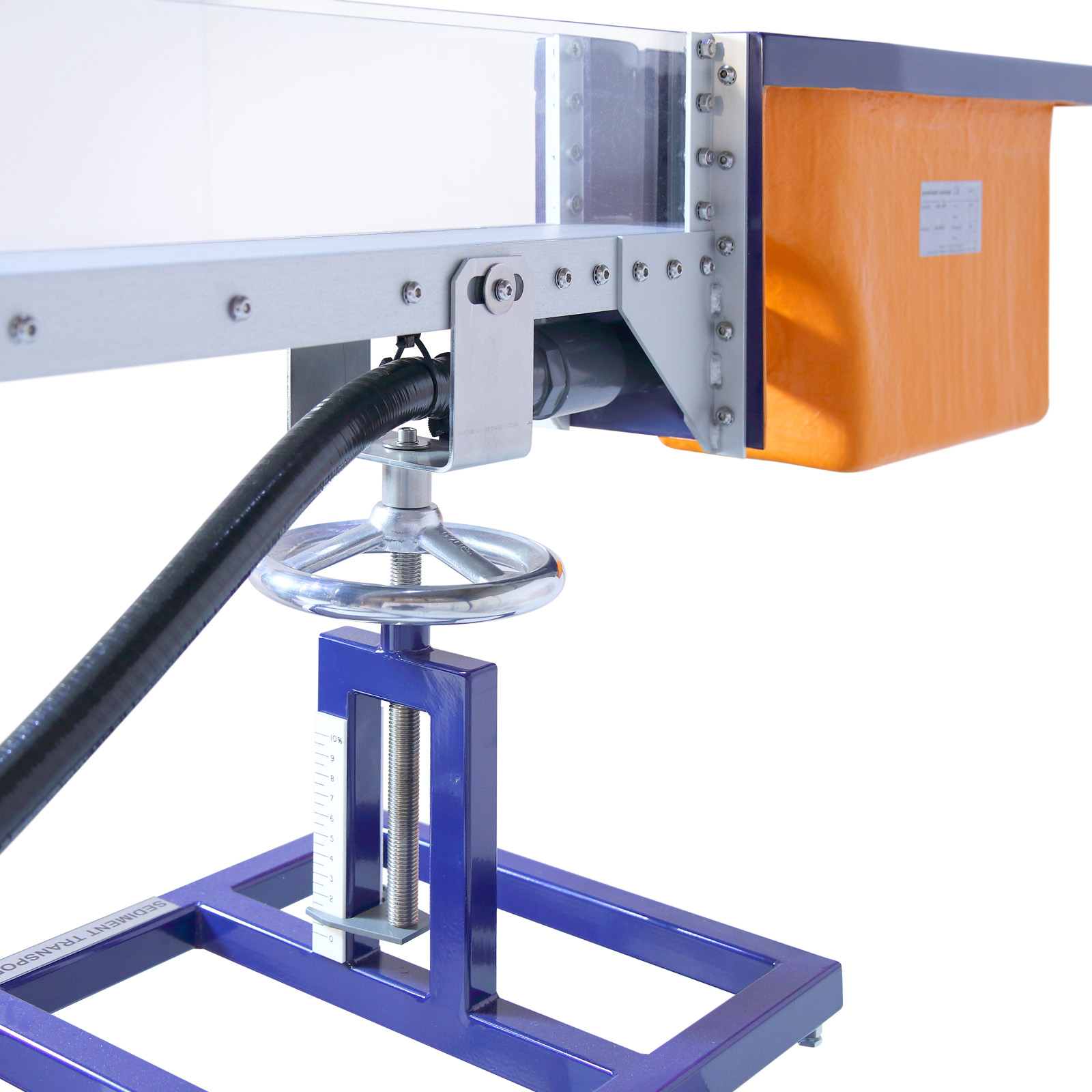
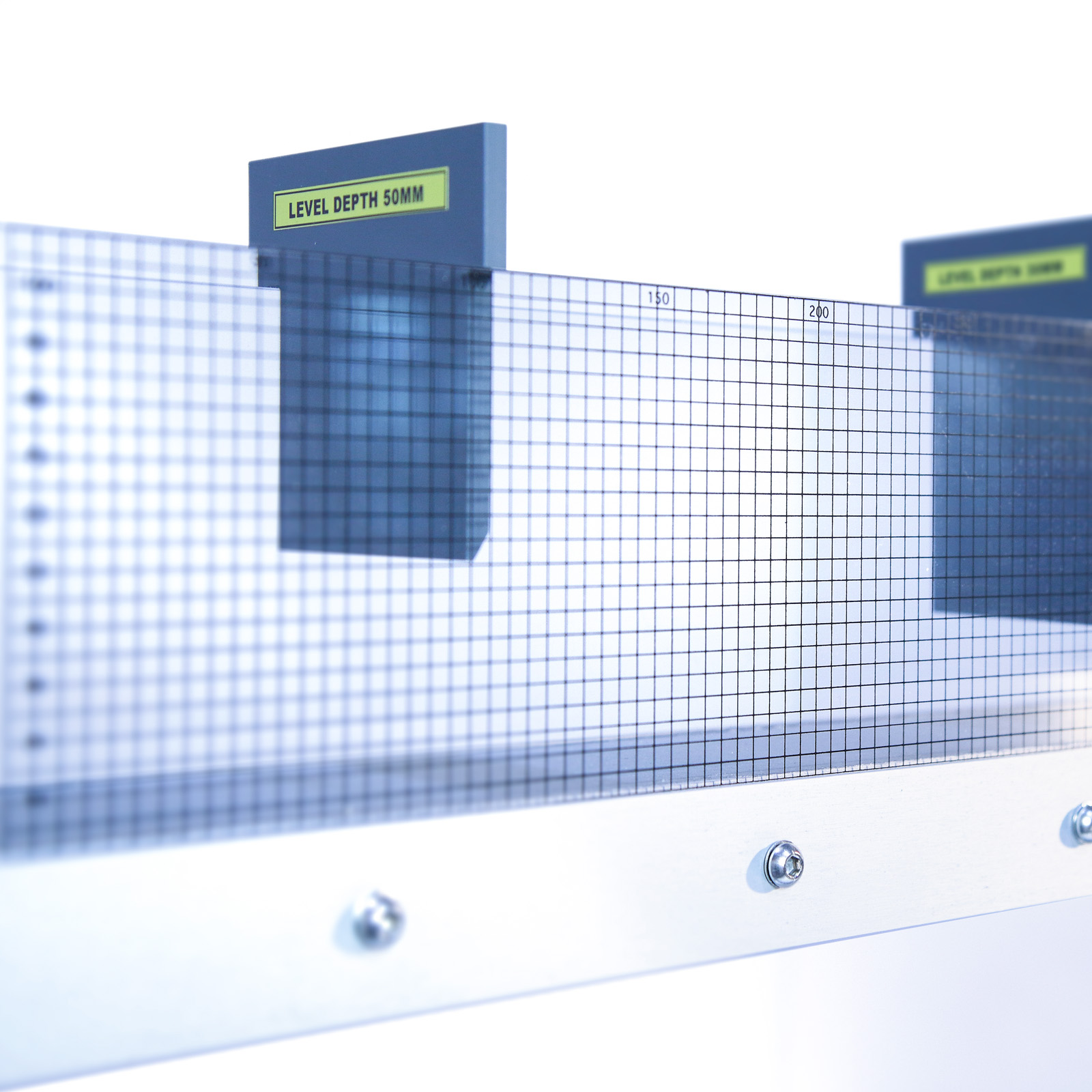
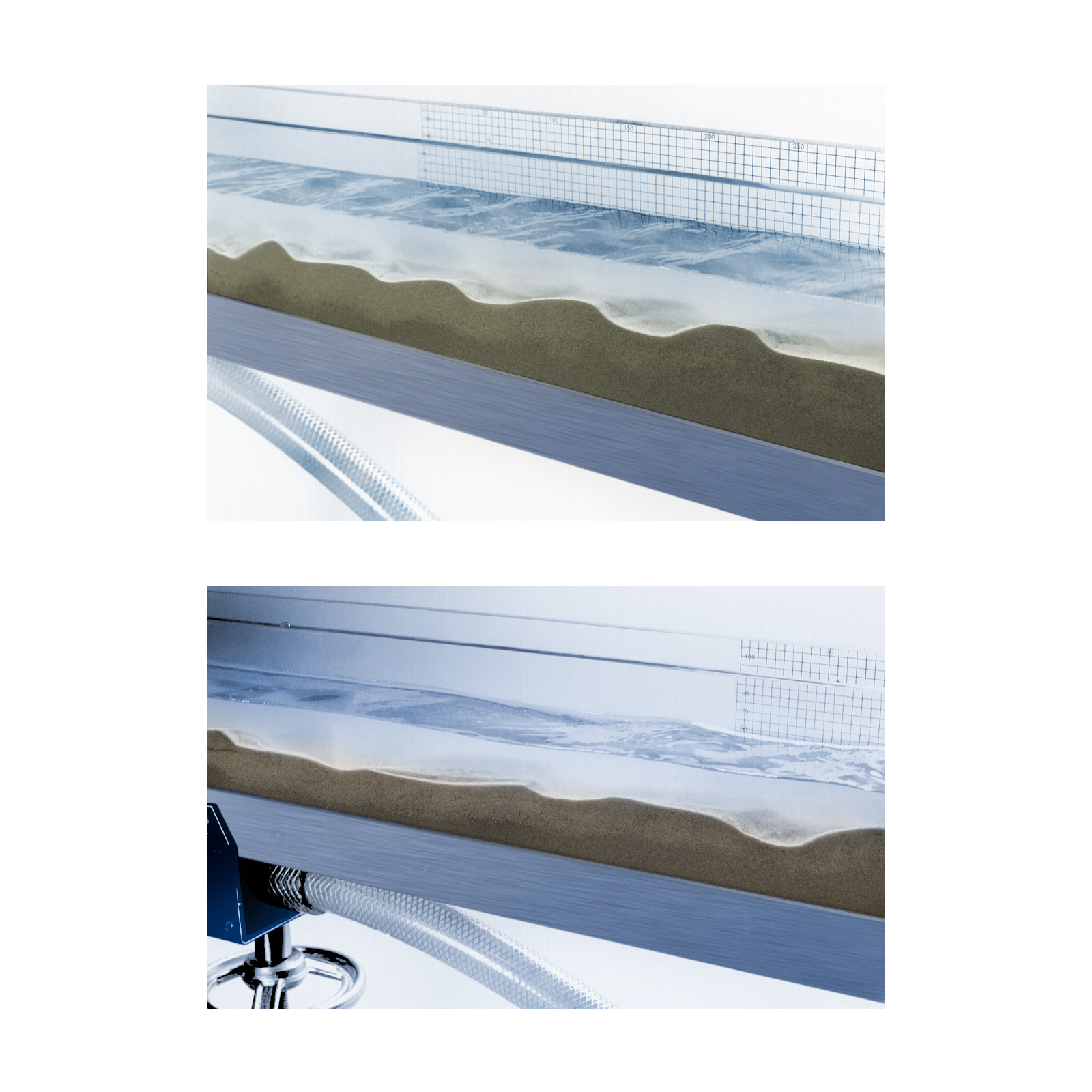
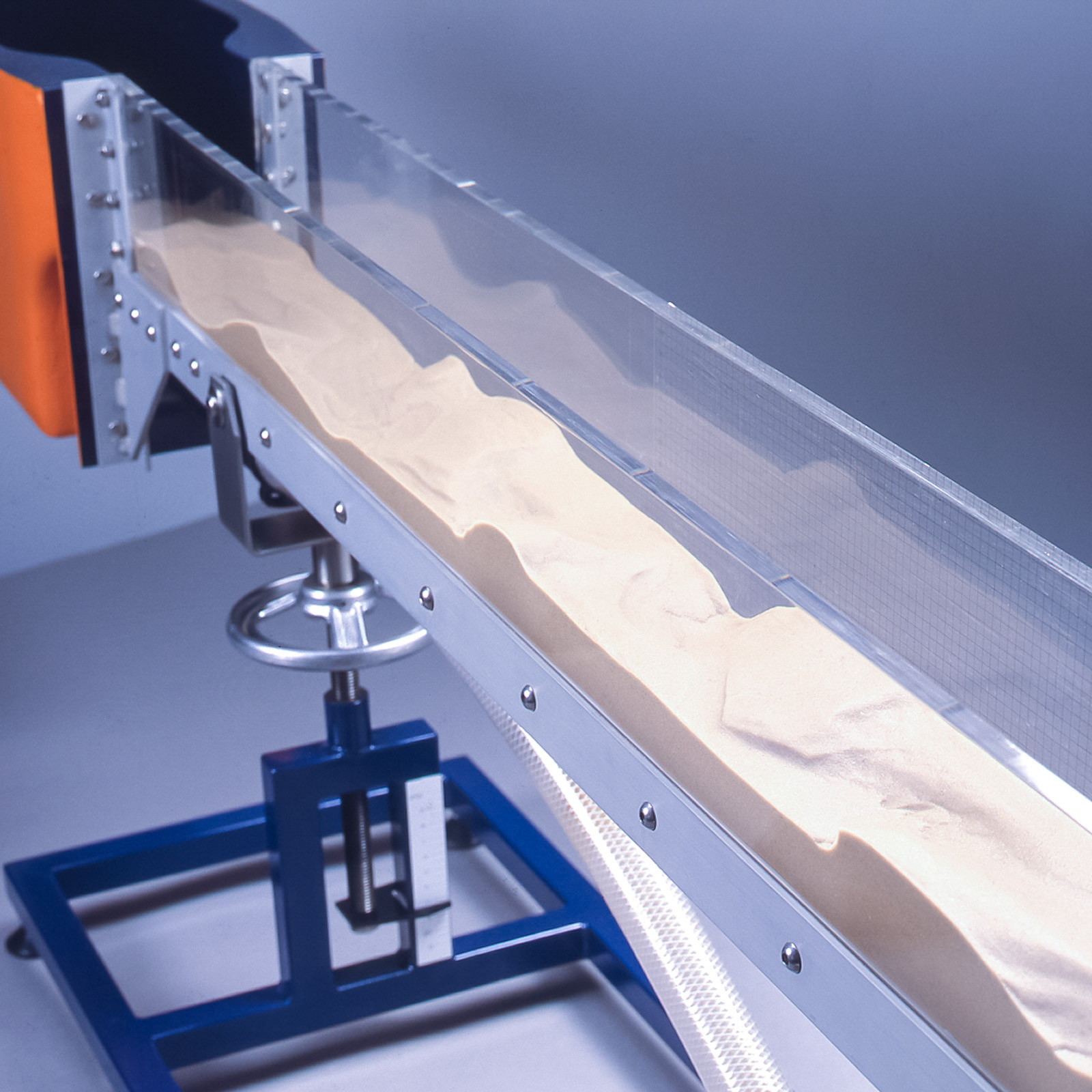
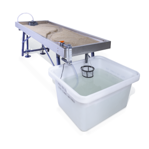
The unit consists of an inclinable channel mounted on a frame, together with a discharge tank and recirculating pump. To commence a demonstration, sand is placed evenly along the channel bed, between the inlet tank and the overfall discharge weir. Water is circulated around the system at one of the three selectable flow rates. The channel slope is adjusted by means of a fine screw jack to which an accurate slope indicator is attached. The channel sides are transparent in order that bed profile changes can be observed and a section of one side is provided with graphical grid markings to permit quantitative assessments to be made of bedform dynamics.
A water level gauge is supplied to measure the head over the channel discharge weir to deduce flow rates from a user generated calibration chart.
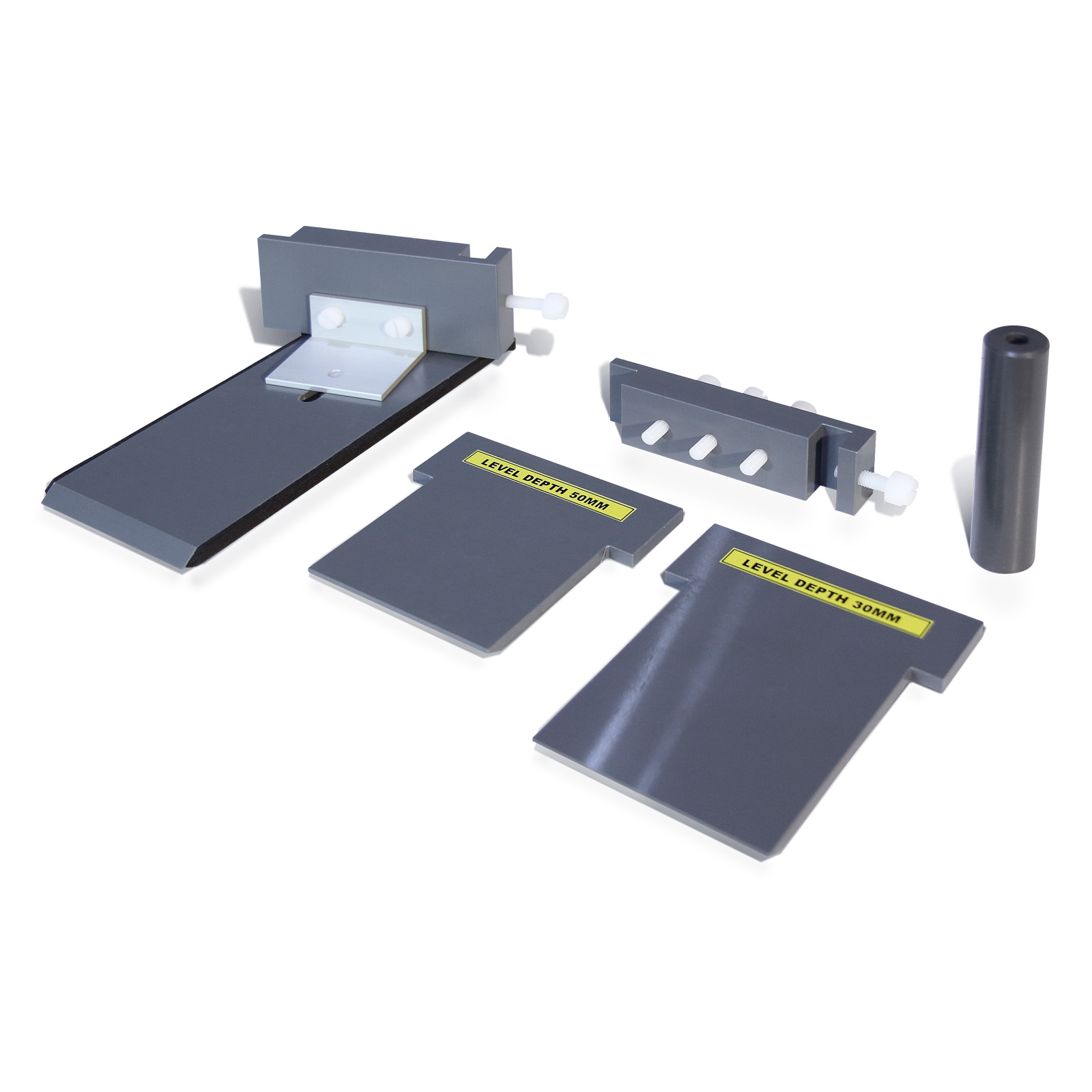
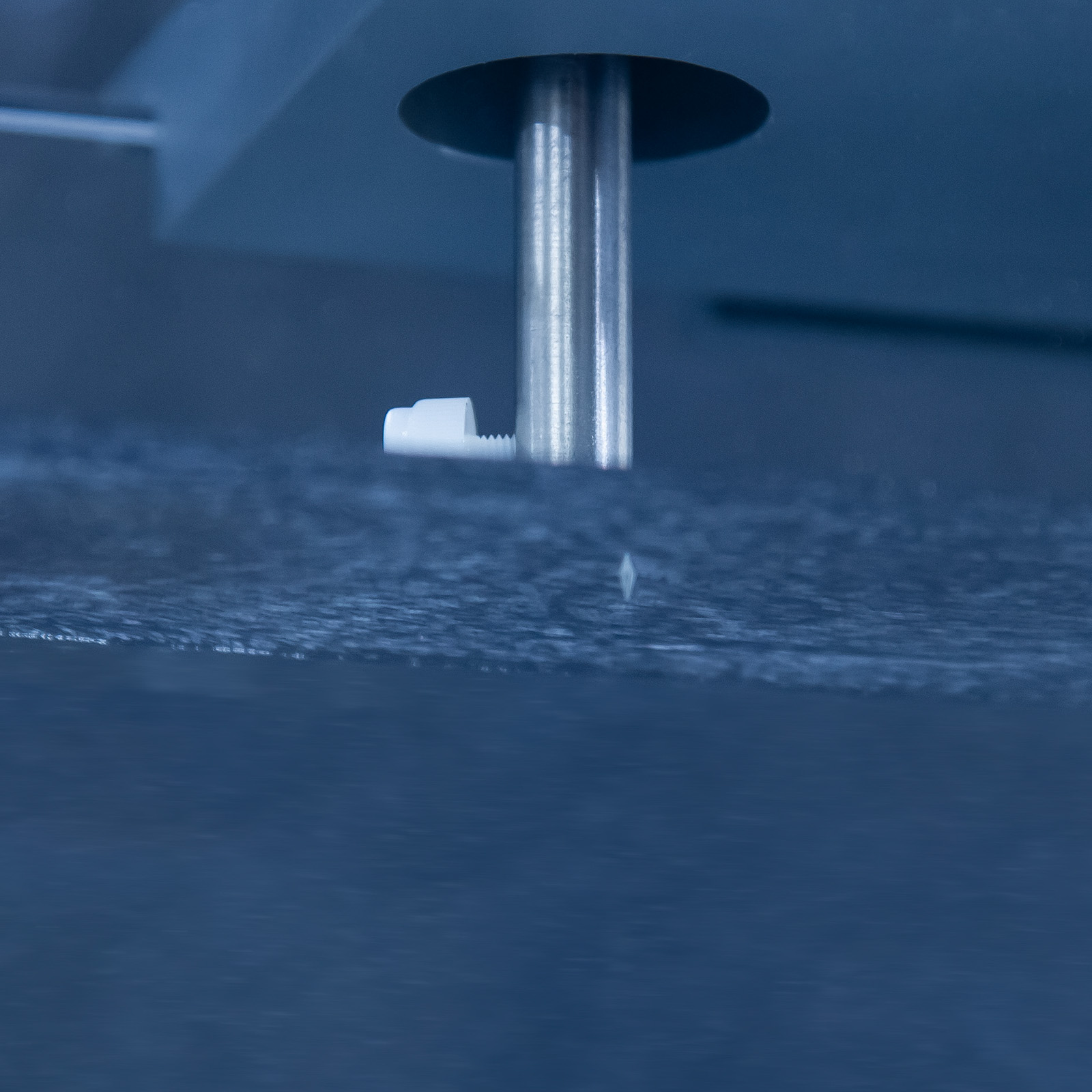
Solid models of a bridge pier and an undershot weir are provided to demonstrate the scour effects on river beds of man-made structures.
Technical Specifications
Channel working section
Length: 1.55m
Width: 0.78m
Depth: 0.11m
Discharge rate
Three fixed flow rates between 0.2 and 0.6 litres/sec, selected by switch on pump
Slope: 0 to 100%
Sediment diameter: 0.1 to 0.3mm
Weight of sand supplied: 15Kg
Weight (including sand and water)
S8-MKII-A: 74Kg
S8-MKII-B: 78Kg
S8-MKII-G: 74Kg
Features & Benefits
Fixed, smooth bed flow:
The flume may be used without sediment on the bed to demonstrate the following flow phenomena and governing equations:
- Tranquil, subcritical flow – movement of surface waves upstream against flow
- Rapid, supercritical flow – dominance of inertial over gravity forces, ‘shock waves’ from flow obstructions
- Hydraulic jump – transition from super to subcritical flow, air entrainment, mixing
- Turbulence – flow visualisation for example by dye injection from a hypodermic syringe (not supplied)
- Flow measurement – using sharp crested weirs
- Governing equations of open channel flow – Reynolds’ number, Froude number, continuity, Bernoulli’s equation, weir equations
Flow over a mobile sandbed:
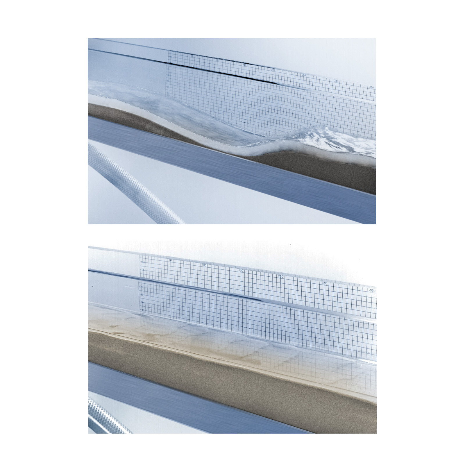
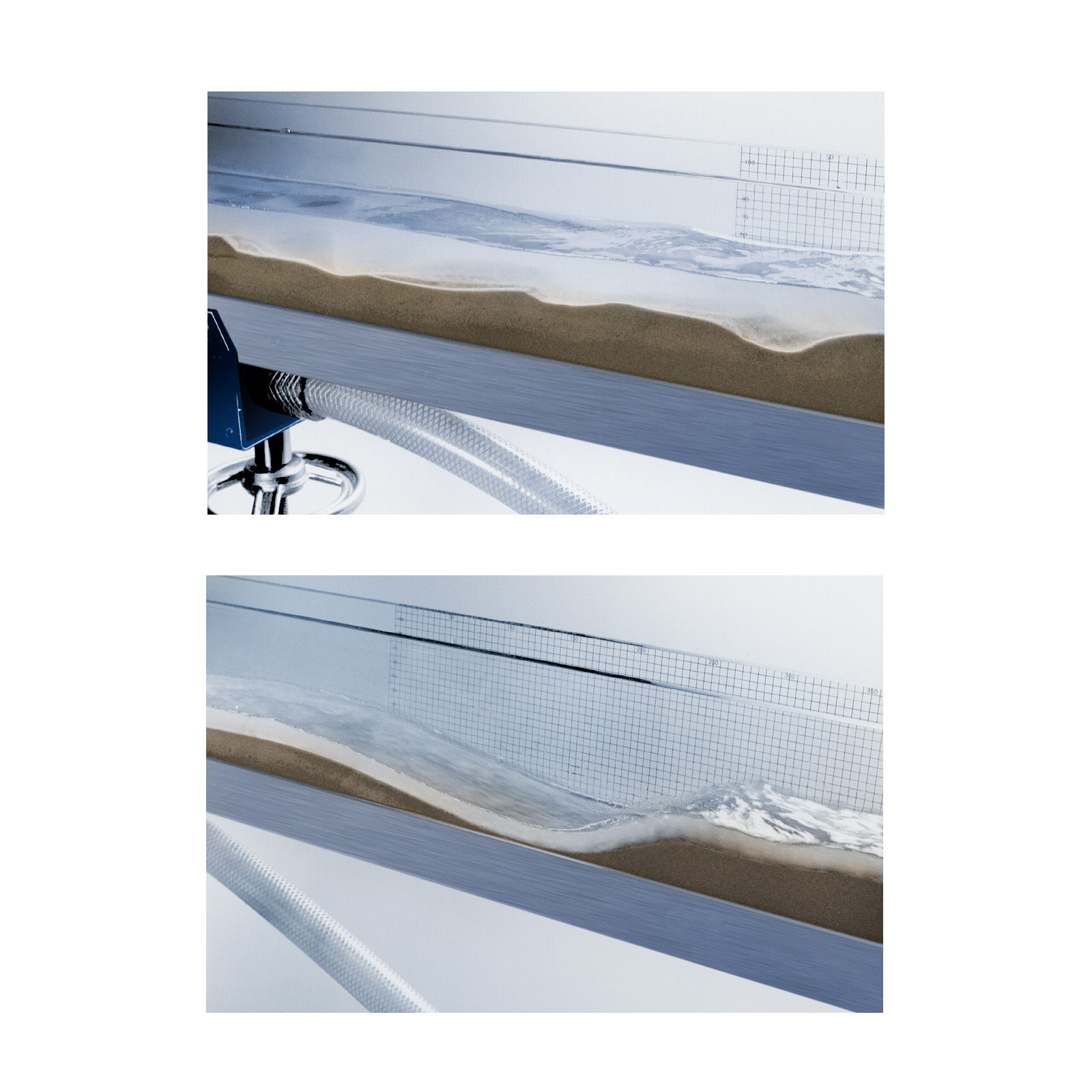
Sequence of bedforms associated with increasing flow intensity and sediment transport rate. The following bedforms are exhibited (as discharge and/or slope are increased):
- Lower regime:
Plane bed (no motion)
Ripples
Ripples and dunes
Dunes
Washed out dunes
- Upper regime:
Plane bed (with motion)
Standing waves
Antidunes
Breaking antidunes
Chutes and pools
Mechanics of sediment transport:
Starting from a plane bed with no motion, the movement of grains can be observed with emphasis on the following:
- Initiation of motion
- Trajectory of initial motion
- Movement by rolling and sliding (contact load)
- Movement by hopping (saltation load)
Depositionary features and facies:
The deposition of sediment load can be observed and the resulting patterns of grains within the sand body (such as cross bedding, foreset beds etc.) may be identified. The significance of such features when found in geological records can be discussed.
Local scour:
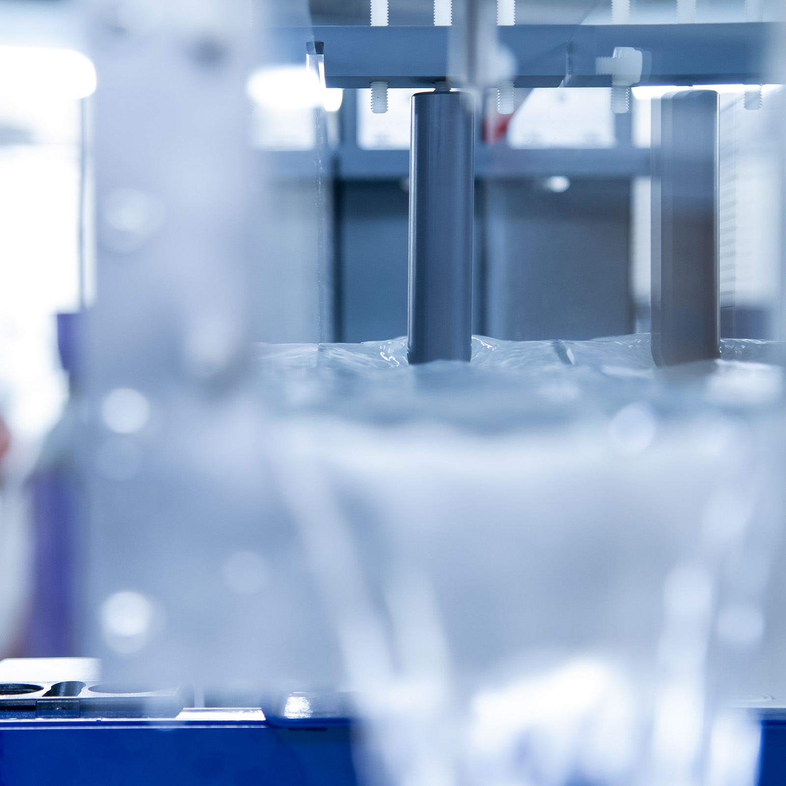
Scour under boils and vortices in the flow is observed under both the lower and upper regime bedforms. Artificial obstructions may be introduced to represent bridge piers, revetments, sills or other man-made structures, and the resulting pattern of scour examined. Two such models are included.
Flow structures:
The structure of turbulence in the flow may be examined using dye injection (dye injector not included). This is particularly interesting for the dune bedform configuration and clearly demonstrates separation on the lee face.
Bedform hysteresis:
If the discharge in the flume changes quickly, there is insufficient time for bedforms to adjust to the new flow regime. Hence, if a flood hydrograph is simulated by increasing and then decreasing the discharge, different depths (stages) will occur for the same discharge on the rising and falling limbs. This effect is of major importance to gauging stations on sandbed rivers. It is easily and clearly demonstrated in the flume.
Computational work:
In addition to illustrating flow and sediment phenomena, the flume can be used for basic data collection and numerical evaluation of the following:
- Flow resistance:
Manning, Chezy and Darcy
Weisbach friction factors for various bedform configurations
- Bedform prediction:
Hjulstrom diagram (velocity)
Bogardi diagram (shields parameter)
Simons and Richardson charts (stream power)
Leeder chart (boundary shear stress)
Movement by suspension (suspended load)
- Initiation of motion:
Hjulstrom’s curve – Shields diagram
Flow over a fixed, gravelbed:
The flume cannot transport gravel, but can be used to investigate flow resistance in gravel and polder bed rivers. The flow resistance coefficients may be calculated using equations (such as those of Bray, Limerinos, Hey, Lacey, Thompson & Campbell, and Bathurst), and the results compared to the actual values obtained by observation. It is recommended that users obtain actual gravel material from local sources (gravel not supplied by Armfield).
- Regimes of fixed bed flow
- Initiation of bedload motion
- Fixed, smooth bed flow
- Flow over a mobile sandbed
- Mechanics of sediment transport
- Investigate sediment transport rate and the relationship between the intensity of the flow and its ability to transport sediment
- Depositionary features
- Demonstrate scour at structures and study erosion effects associated with channel constrictions and flow around structures in the channel
- Flow structures
- Hysteresis of bedforms during changing stage
- Investigate flow resistance in a gravel bed and illustrate the difference between gravel bed flow and the sand bed flow
- A transparent, inclinable flow channel through which water can be recirculated by a pump over a mobile bed to demonstrate the whole range of bedforms from incipient particle movement to bed washout
- Three different discharge rates can be selected and measured within the range 0.2 to 0.6 litres/sec
- The channel slope can be adjusted within the range 0-10%
- The working section of the channel is 1.55m long, 78mm wide and 110mm deep
- The equipment is self-contained and may be bench mounted in either the classroom or laboratory by virtue of its portability
- A model undershot weir and bridge pier are included for local erosion demonstrations
- A water level gauge is supplied to calibrate the overshot weir
Electricity supply:
S8-MKII-A: 220-240V/1ph/50Hz
S8-MKII-B: 120V/1ph/60Hz
S8-MKII-G: 220V-240V/1ph/60Hz
First fill of water (approx. 22 litres)
PACKED AND CRATED SHIPPING SPECIFICATIONS
Volume: 0.6m³
Gross Weight: 100kg
Length: 2.5m
Width: 0.4m
Height: 1.1m (to top of point gauge)
- S8-MKII-A
- S8-MKII-B
- S8-MKII-G
