HT20X – Conductivity of Liquids and Gases
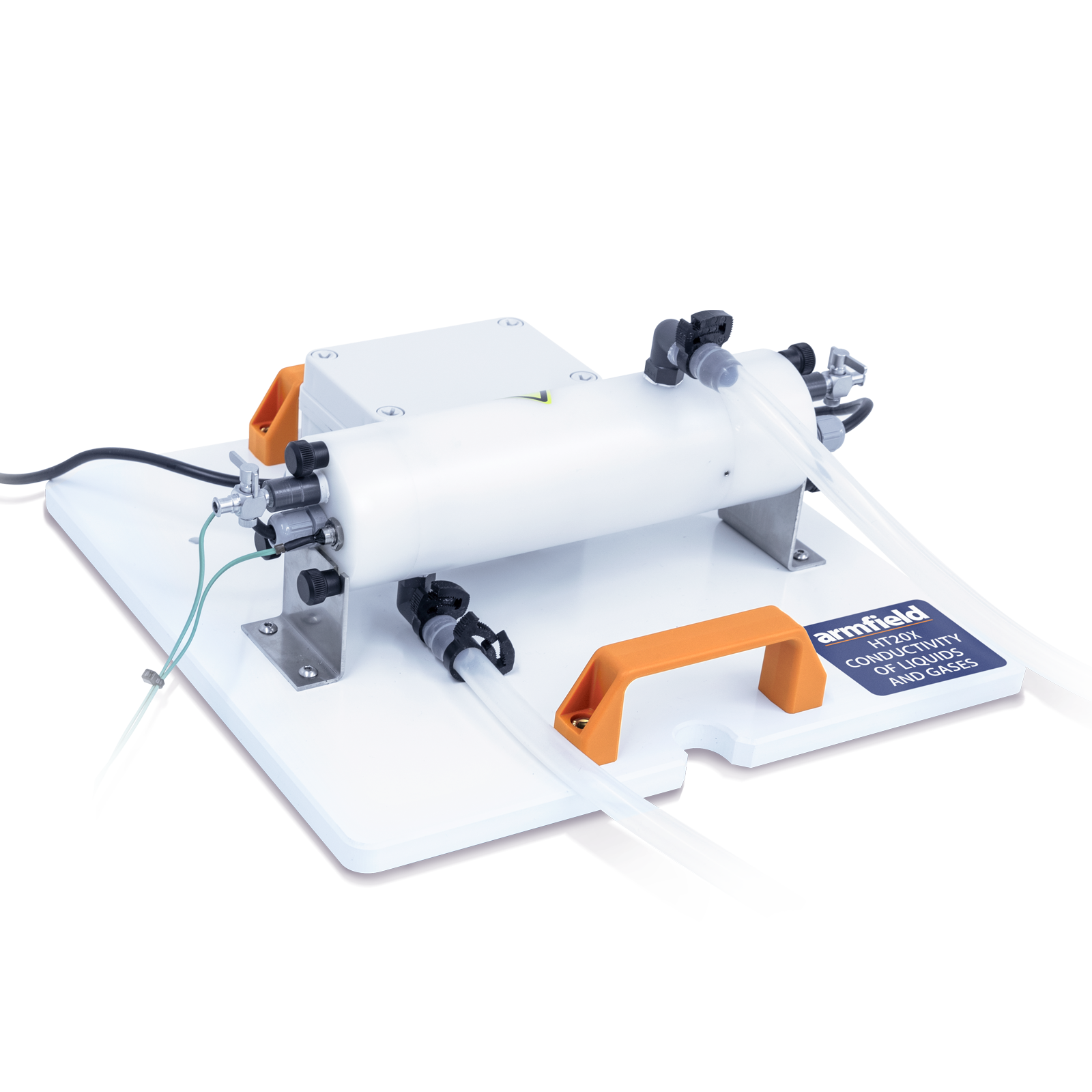
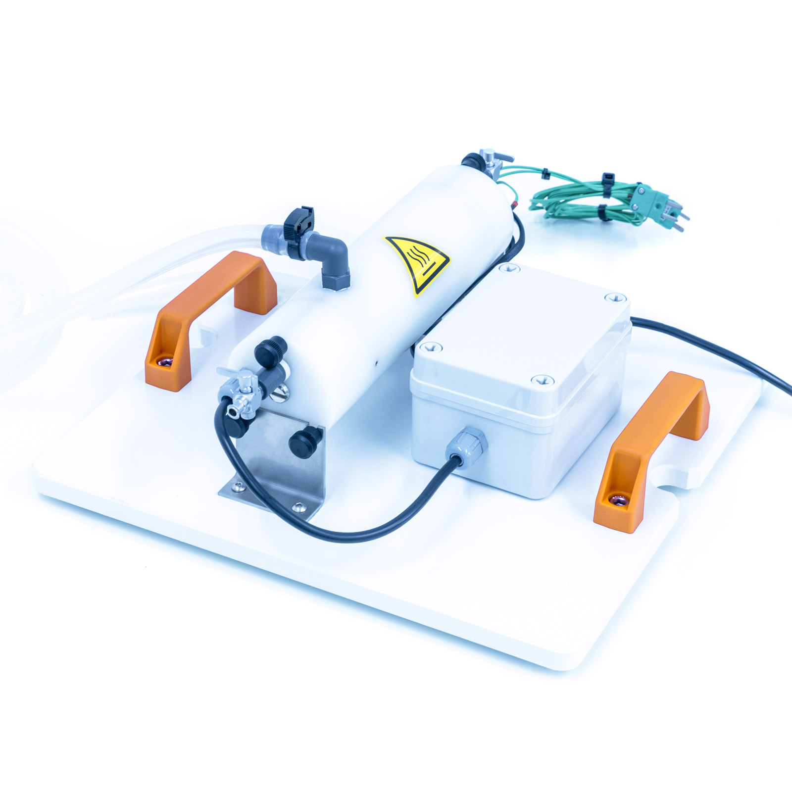
The Armfield Conductivity of Liquids and Gases unit has been specifically designed to enable students to measure and compare the thermal conductivities of various liquids and gases. It’s designed to facilitate quick and effective cleaning and to minimise thermal losses.
Description
The Armfield Conductivity of Liquids and Gases unit has been specifically designed to enable students to measure and compare the thermal conductivities of various liquids and gases. It’s designed to facilitate quick and effective cleaning and to minimise thermal losses.
The unit comprises a cylindrical, electrically heated, nickel-plated aluminium core surrounded by a nickel-plated aluminium sleeve. The core and the sleeve are arranged so that a uniform narrow annular gap is created between the two parts, which is filled by the liquid or gas to be analysed.
The temperature on each side of the fluid is measured by thermocouples in the surface of the core and the sleeve.
The HT10X service unit is provided with an electronic proportioning valve and flow meter to control and measure the water flow. The unit incorporates an insulated jacket to minimise heat exchange from and to the atmosphere.
The fluid to be tested is injected into the annular gap between the heated core and the cooled jacket using a hypodermic syringe.
Measurement of the temperature difference between the heated and cooled surfaces together with the power supplied to the heater (measurement of DC voltage and current) using HT10X allows the conductivity of the fluid to be calculated. The surface area and thickness of the fluid sample remain constant during all tests.
Technical Specifications
Thickness of fluid sample – 0.5mm (Fixed by the annular gap)
Nominal heat transfer area – 1.225 x10⁻² m²
Gas / liquid sample volume – 6.126ml
Maximum heater power – 200W at 24V
Maximum operating temperature – 90°C (limited by integral thermostat)
Features & Benefits
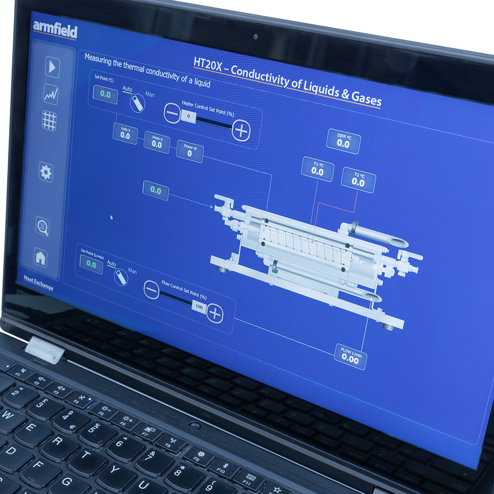
Software: A full armBus educational software suite is provided with the HT10X for all the Armfield heat transfer accessories.
Individual experiment interfaces and displayed data types vary to match selected experiment accessories, common examples are listed below:
- Temperatures and other signals such as flow rates, heater voltage and current are displayed on a diagrammatic representation of the equipment
- Control outputs are operated by a control slider or typing in a value between 0 and 100%. Sensor values are read directly in engineering units
- PID automatic control option is available, permitting the temperature set-point to be achieved quickly and precisely, coping with disturbance rejection
- A maintenance screen allows for PID parameter adjustment and thermocouple calibration
- Data from the sensors are logged into a spreadsheet format, with operator control over the sampling intervals (or ‘single-shot’)
- Sophisticated graph-plotting facilities are provided, including plotting of both measured and calculated values
- Graphs update in real-time as the samples are being taken
- Processing of measured values to obtain calculated values is linked to the questions and answers to ensure student understanding
- Experiment data samples are saved, or exported in Microsoft Excel format
- Real-time sensor data is displayed independently from the data logging. It is possible to check the recent history graphical display to inspect the temperature stability prior to taking a sample
- Understanding the use of the Fourier rate equation in determining the rate of heat flow by conduction through liquids or gases
- Measuring the constant of proportionality (the thermal conductivity k) of different liquids such as water and glycerol
- Calibrating the unit for heat losses using a gas, such as air with known thermal conductivity, then measuring the temperature difference across different gases, such as carbon dioxide and helium to determine their thermal conductivity k
Note: Flammable, explosive, corrosive or toxic liquids and gases must not be used in the equipment.
- Thickness of the fluid sample is restricted to 0.5mm to minimise convection in the fluid sample
- Concentricity of the heated and cooled surfaces is accurately maintained using a spiral insulator
- Trapped bubbles of the previous liquid or gas sample are prevented by the spiral flow path when injecting a different liquid or gas
- ArmSoft software is supplied, with separate exercises for determining the thermal conductivity of liquids and gases
- A small-scale accessory to allow students to measure the thermal conductivity k of various liquids and gases
- Comprises a water-cooled, aluminium outer sleeve surrounding a heated aluminium core creating an annular gap 0.5mm wide that is filled with the fluid under test
- Nominal heat transfer area 1.225 x 10⁻² m2
- Gas or liquid sample volume 6.126ml
- Heater power is variable up to 200W at 24V using the Heat Transfer Service Unit
- Overheating is prevented by an integral thermostat
- Heater can be voltage or PID controlled allowing for the temperature set-point to be achieved rapidly and maintained within 0.1°C.
- Two k-type thermocouples measure the temperature gradient across the liquid or gas under test
- Nickel-plated surfaces to minimise radiation losses, narrow annular gap to minimise convection losses and thermally insulated to minimise heat exchange with the atmosphere
- Includes a pressure regulator to provide a steady flow of cooling water
- Computer-controlled unit includes an electronic proportioning valve and flow meter to vary and measure the flow of cooling water
- A comprehensive instruction manual describing how to carry out the laboratory teaching exercises to measure thermal conductivity as well as installation and commissioning is included
HT10X Heat Transfer Service Unit
All electrical requirements are obtained from the service unit
PACKED AND CRATED SHIPPING SPECIFICATIONS
Volume: 0.04m³
Gross Weight: 8kg
Length: 0.30m
Width: 0.25m
Height: 0.16m
HT20X
