CM14 – Axial Flow Gas Turbine
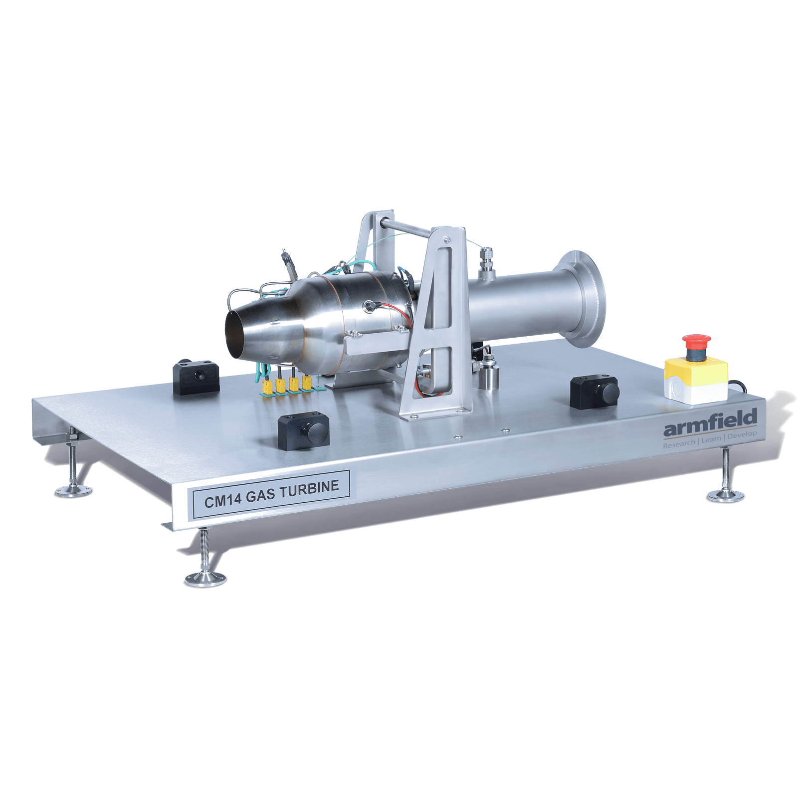
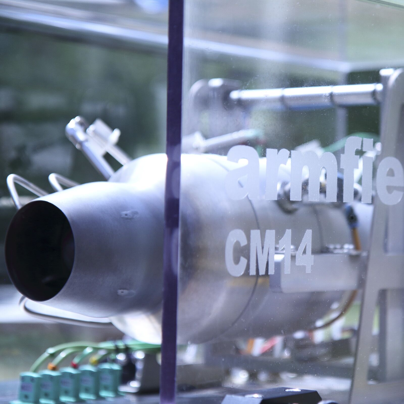
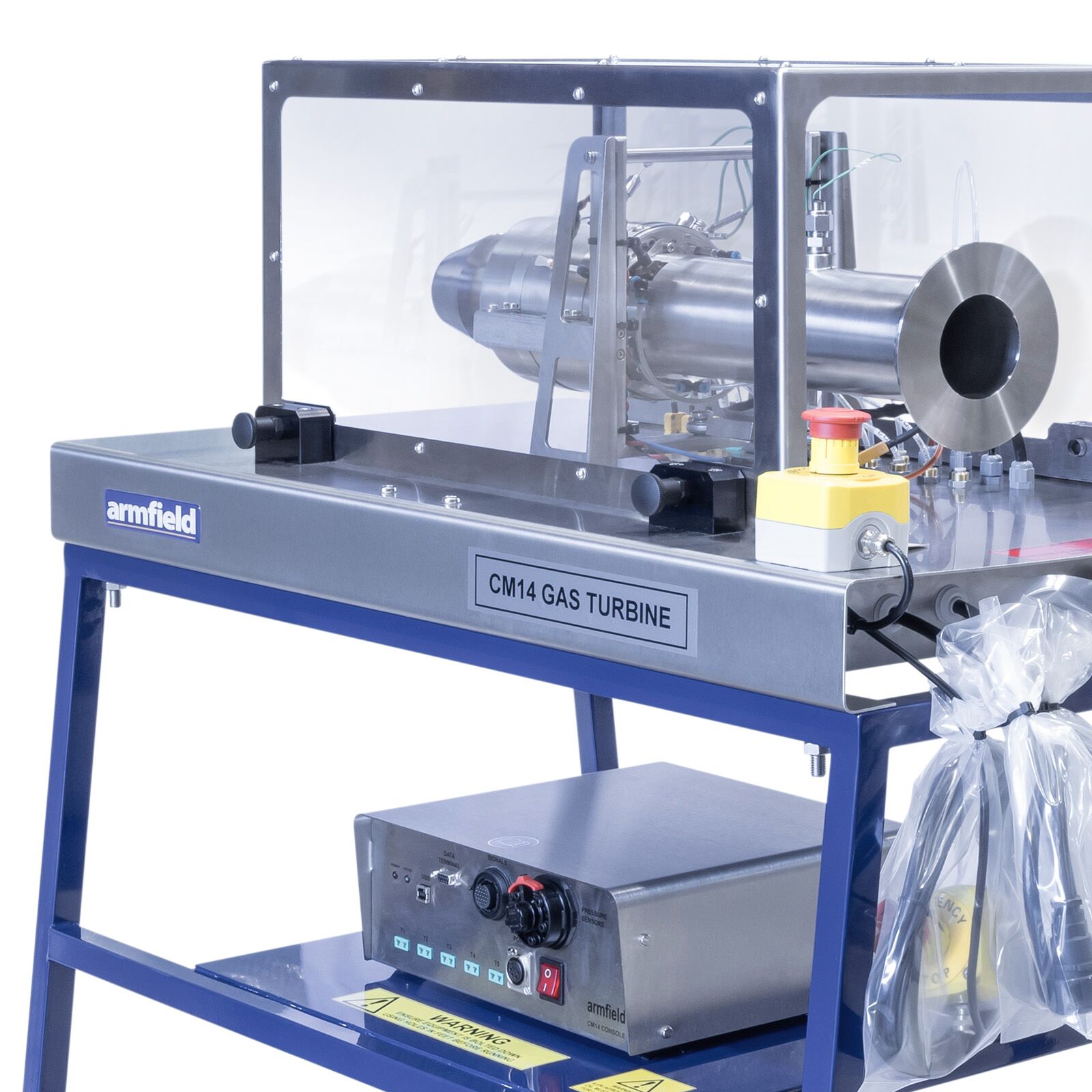
The CM14 Axial Flow Turbine Engine is securely fixed to a robust metal frame with a steel & Perspex case to reduce the noise and ensures engine stability while allowing precise measurement of the thrust it produces.
An electronic pre-programmed controller continuously monitors the engine, maintaining safe operating conditions at all times. The engine is controlled via dedicated software, offering users a graphical interface for real-time monitoring and seamless operation.
Description
The CM14 axial flow turbine engine, has been integrated into a sturdy metal frame that holds it firmly, while enabling accurate measurement of the thrust produced by the engine.
Electronic preprogrammed controller constantly supervises the engine, ensuring safe operating conditions at all times.
The engine is controlled via the software, which provides users with a graphical interface for real-time monitoring and operation.
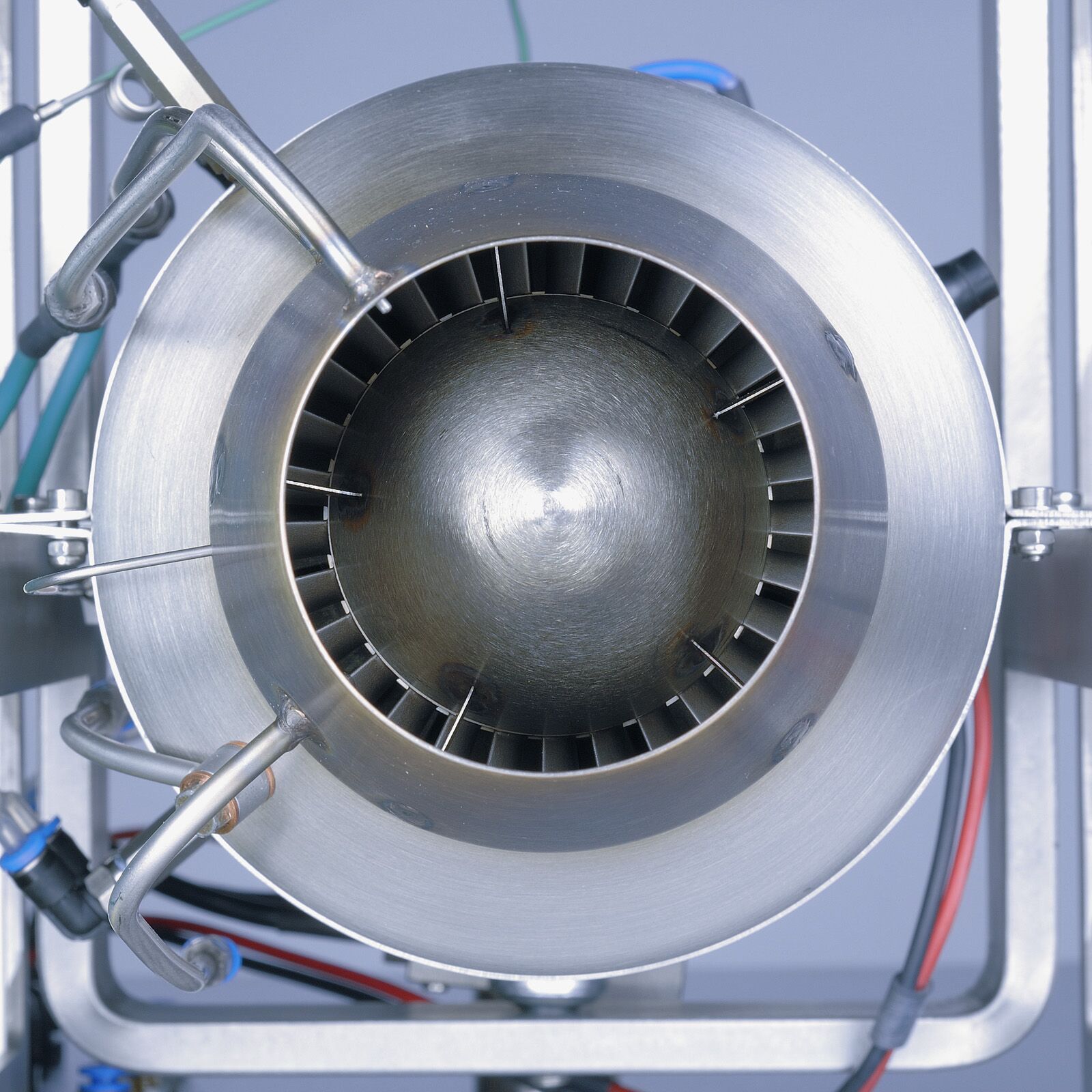
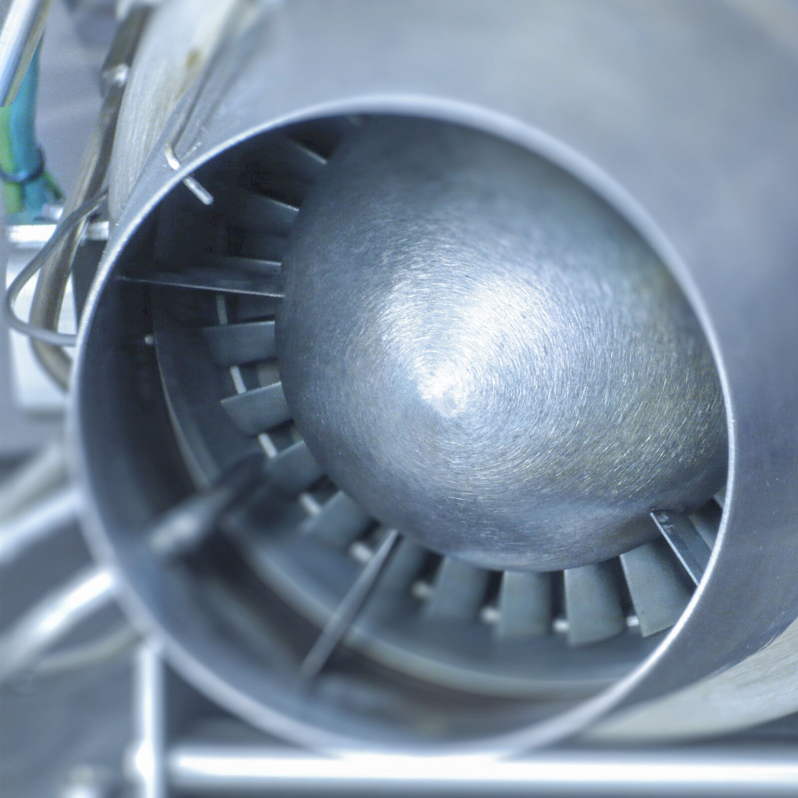
The engine is the compact Olympus HP E-start turbine engine, comprising a single-stage radial compressor, an annular combustion chamber and a low-mass, high-performance axial flow turbine.
The engine has been integrated into a sturdy metal frame that holds it firmly, while enabling accurate measurement of the thrust produced by the engine.
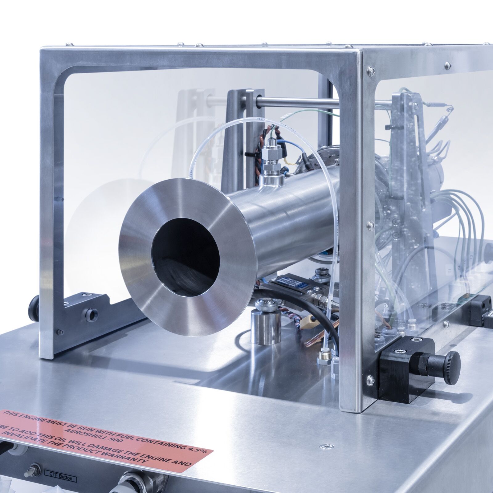
The engine inlet has been replaced with a custom fabricated frontal duct, to enable the air mass flow rate to be accurately measured.
An electronic preprogrammed controller constantly supervises the engine, ensuring safe operating conditions at all times.
The engine is controlled via the software, which provides users with a friendly graphical interface for real-time monitoring and operation.
This software controls the engine speed via an electronically controlled high-precision fuel gear pump. This method gives a very fast engine response.
The engine is easy to start and stop from the software interface and automatic, optimal start-up and power-down sequences are already set to assure minimum mechanical stresses. There is no requirement for compressed air supply or propane gas to start the engine.
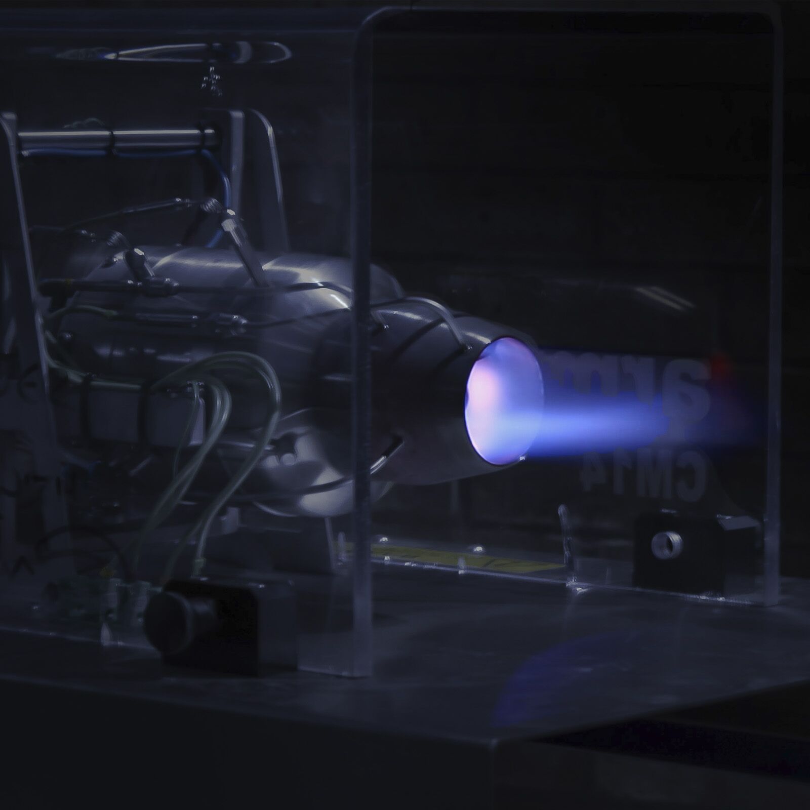
A tough, transparent polycarbonate screen is fitted in order to make the apparatus completely safe but still provides excellent visibility of the engine when in use. The screen is removable, enabling full access to the engine and instrumentation.
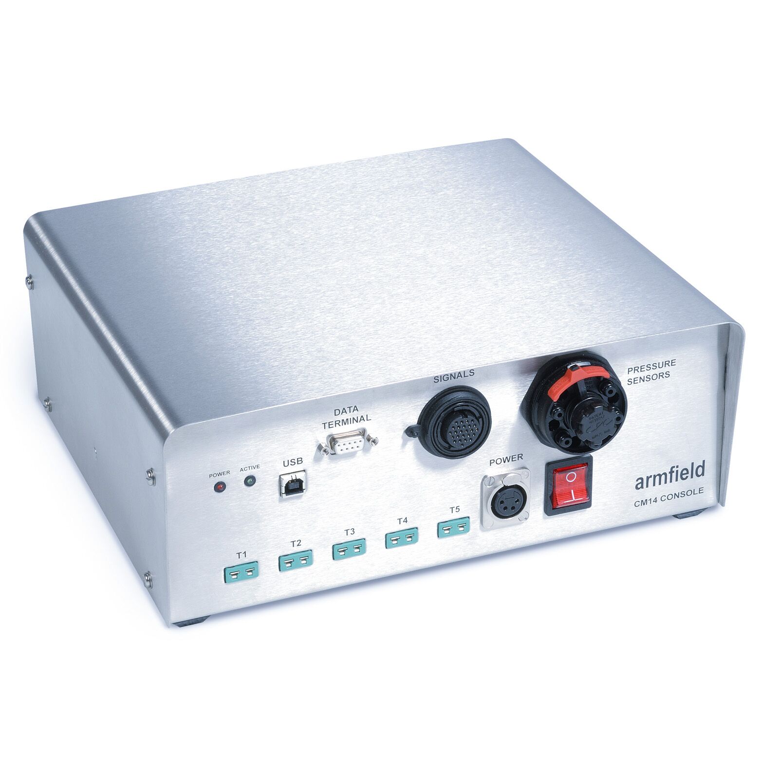
The engine software runs on a personal computer, requiring only a single USB interface between the electronic console and the PC. This enables simple installation into a test cell or soundproof enclosure.
Technical Specifications
Performance specification
- Typical fuel: One of the following choices (See requirements for detailed list)
– Jet A-1
– JP-4/Kerosene
- Exhaust gas temperature: 800°C typical
- Mass flow: 450 g/s
- Ignition system: Glow plug
- Compressor type: Single-stage radial
- Turbine type: Single-stage, low-mass axial flow
- Engine rpm: 105,000rpm typical
- Engine mount: Single pivot point
Features & Benefits
- Complete aeronautical axial flow gas turbine engine
- Full instrumentation and sensors
- Automatic start & shut down procedures
- Fully software controllable
- Easy installation into a test cell (single USB interface)
- High-performance centrifugal compressor
- High maximum rpm
- Fast response to speed changes
- Single point pivot on engine mounting enables accurate thrust measurement
- No need for external lubrication system; lubricant is mixed with the fuel
- No need for external battery and charger – a standard domestic outlet is used to power the CM14
- Can be fuelled with common paraffin or kerosene – no need for difficult-to-find aviation fuel
- Simple ignition system, based on a common Rossi R8 glow plug
- Data acquisition and educational software included
- Small-scale equipment minimises laboratory space needed
- Fully tested for high performance and safety
- Tough, transparent polycarbonate safety screen
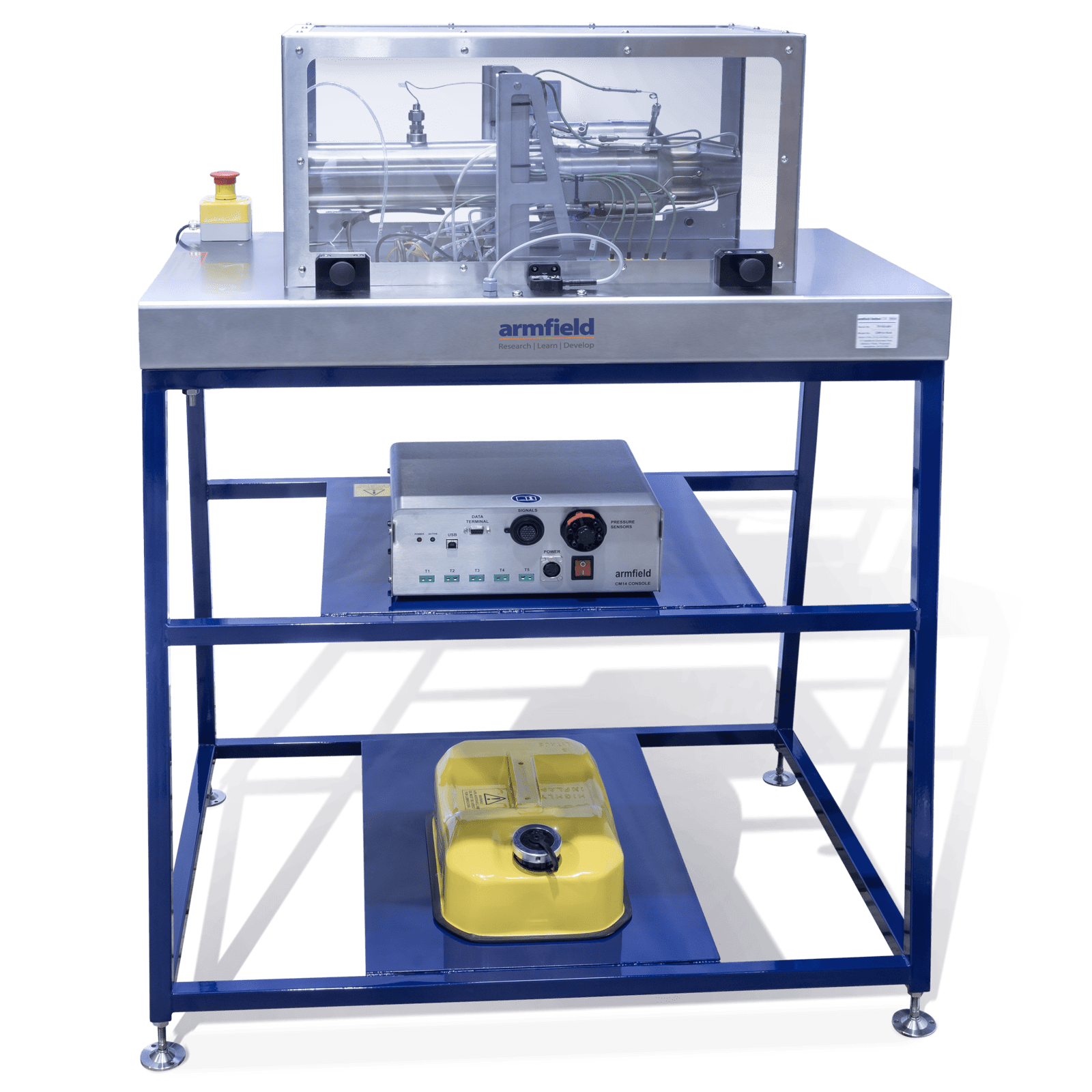
- An optional floor-standing frame is available to house the unit together with its fuel tank and electronic console
- New improved starting system, no need for compressed air or propane gas
- To estimate the thrust output from the engine, using the momentum equation, and to compare this result to the measured thrust
- To estimate the actual thermodynamic cycle experienced by the flow throughout the engine and represent it in the form of the Temperature vs. Specific Entropy diagram
- To calculate efficiencies of each stage of the engine and the back work ratio
Nozzle
- Exit total temperature
- Fuel flow
- Air flow
- Shaft speed
- Thrust
Compressor
- Exit total pressure
- Exit pressure
- Exit total temperature
Inlet Duct
- Inlet temperature
- Inlet pressure
Turbine
- Entry total temperature
- Entry total pressure
- Exit total temperature
- Exit total pressure
The data display and acquisition system requires a PC running Windows 7 or above with a USB port (computer not supplied).
Sensors are provided to measure thrust (direct from a load cell), fuel flow, engine rpm, plus pressure and temperature at each stage of the engine.
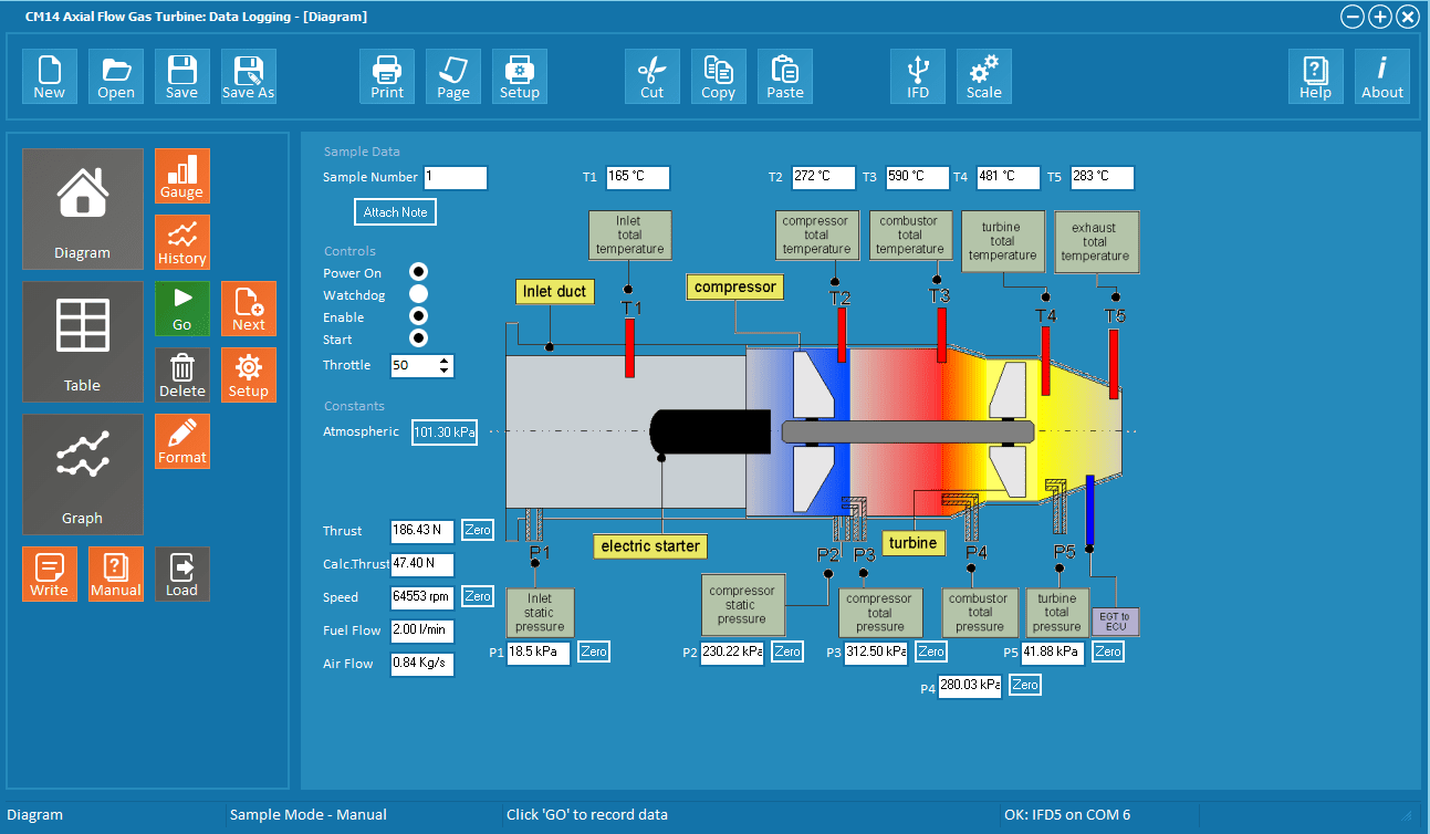
The data from these sensors is passed to the PC on the USB interface and is displayed using the software provided. The software estimates the thrust from the fuel flow, temperature and pressure readings. This can be compared with the measured thrust.
The user has access to a wide range of data acquisition, graph-plotting and display functions. As well as the standard graph-plotting functions, a special routine has been written to display H – S diagrams (Entropy – Enthalpy diagrams), which are of particular interest in thermodynamics.
Full help text is included on both the operation of the equipment and the theoretical background.
- An aeronautical axial flow gas turbine engine mounted on a stainless steel plinth, suitable for bench mounting. An electronic console and 5l ‘explosafe’ fuel tank are also provided
- An optional mounting frame is available for floor-standing operation
- The engine has a maximum speed in excess of 100,000rpm and generates a thrust of at least 195N
- Full instrumentation to measure rpm, thrust, temperature and pressure at each stage of the jet engine
- Stainless steel air inlet duct to measure air flow
- The engine is easy to start, without the need for propane gas or compressed air
- The equipment is fully controlled from a user-supplied PC, which must be running Windows 7 or later. The software includes powerful educational features together with sophisticated graph-plotting and data logging capability
- Connection to the PC is via a single USB port, thus providing simple installation
Single-phase electricity for the battery charger and instrumentation
- CM14-A/CM14-10-A: 220-240V / 1ph / 50Hz
- CM14-B/CM14-10-B: 115V / 1ph / 60Hz
- CM14-G/CM14-10-G: 230V / 1ph / 60Hz
Hearing Protection
Extractor
Software
The user must have a PC with a USB port, running Windows 7 or above.
The ArmSOFT software enables the operator to control the fan speed 0 to 100%. Feedback from the sensors is then displayed in real time for the end user with simultaneous data logging.
The data trend is also displayed graphically in real time and can be exported to another platform such as Excel for further analysis.
Fuel
(Mix with 4,5% of Aero shell, 1 litre supplied with unit)
- Jet A to ASTM D-1655 or TS-1
- Jet A-1 to ASTM D-1655 or TS-1 or DEF STAN 91-91
- Jet B to ASTM D6615
- JP-5 to MIL-PRF-5624S Grade JP-5 or DEF STAN 91-86 AVCAT/FSII or NATO Code F-44
- JP-8 to MIL-T-83188D Grade JP-8 or DEF STAN 91-87 AVTUR/FSII or NATO F-34
- Kerosene to BS EN 2869:2010 Class C2
Installation
It is recommended that the engine test stand be installed in a dedicated test cell, fitted with air extraction and sound deadening. Alternatively outdoor running is possible with suitable ground fixing.
The control computer can then be installed in an adjacent area. Installation in this manner is made as simple as possible, as no physical connection between the control station and the CM14 is required other than a USB cable.
A 5m USB cable is supplied with the equipment.
PACKED AND CRATED SHIPPING SPECIFICATIONS
CM14
Volume: 1.2m³
Gross Weight: 150Kg
CM14-10
Volume: 3.2m³
Gross Weight: 300Kg
Plinth only
Length: 0.36m
Width: 0.51m
Height: 0.88m
Full installation on frame
Length: 1.185m
Width: 0.51m
Height: 0.88m
CM14 Axial Flow Gas Turbine Engine (bench mounting)
CM14-10 Axial Flow Gas Turbine Engine (complete with floor stand)
- CM14-A/CM14-10-A: 220-240V / 1ph / 50Hz
- CM14-B/CM14-10-B: 115V / 1ph / 60Hz
- CM14-G/CM14-10-G: 230V / 1ph / 60Hz
