C7 MkII Pipe Surge And Water Hammer Apparatus
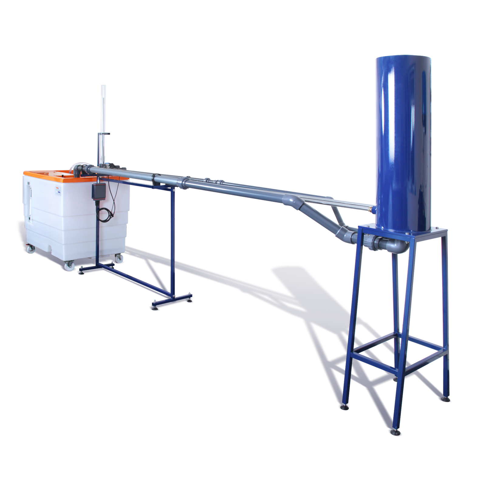
This free-standing accessory to the F1-10 Hydraulics Bench clearly demonstrates the difference between the phenomena of pipe surge water hammer and how each is created.
Description
The equipment is free-standing and comprises two stainless steel test pipes connected to a constant head tank with the necessary connections to an F1-10 Hydraulics Bench.
Pipe surge demonstrations are conducted using the first test pipe, which incorporates a transparent surge shaft with scale and a lever-operated valve at the discharge end. An additional valve downstream enables the flow through the test pipe to be varied before closing the lever-operated valve. An electronic pressure sensor located at the base of the surge shaft enables the low-speed transients in water level to be measured.
Water hammer demonstrations are conducted using the second test pipe, which incorporates a fast-acting valve at the discharge end. An additional valve downstream enables the flow through the test pipe to be varied before closing the fast-acting valve.
The unique fast-acting valve, specifically designed by Armfield, enables water hammer to be generated in a relatively short length of straight pipe because of the extremely short closure time achieved using a trigger actuator.
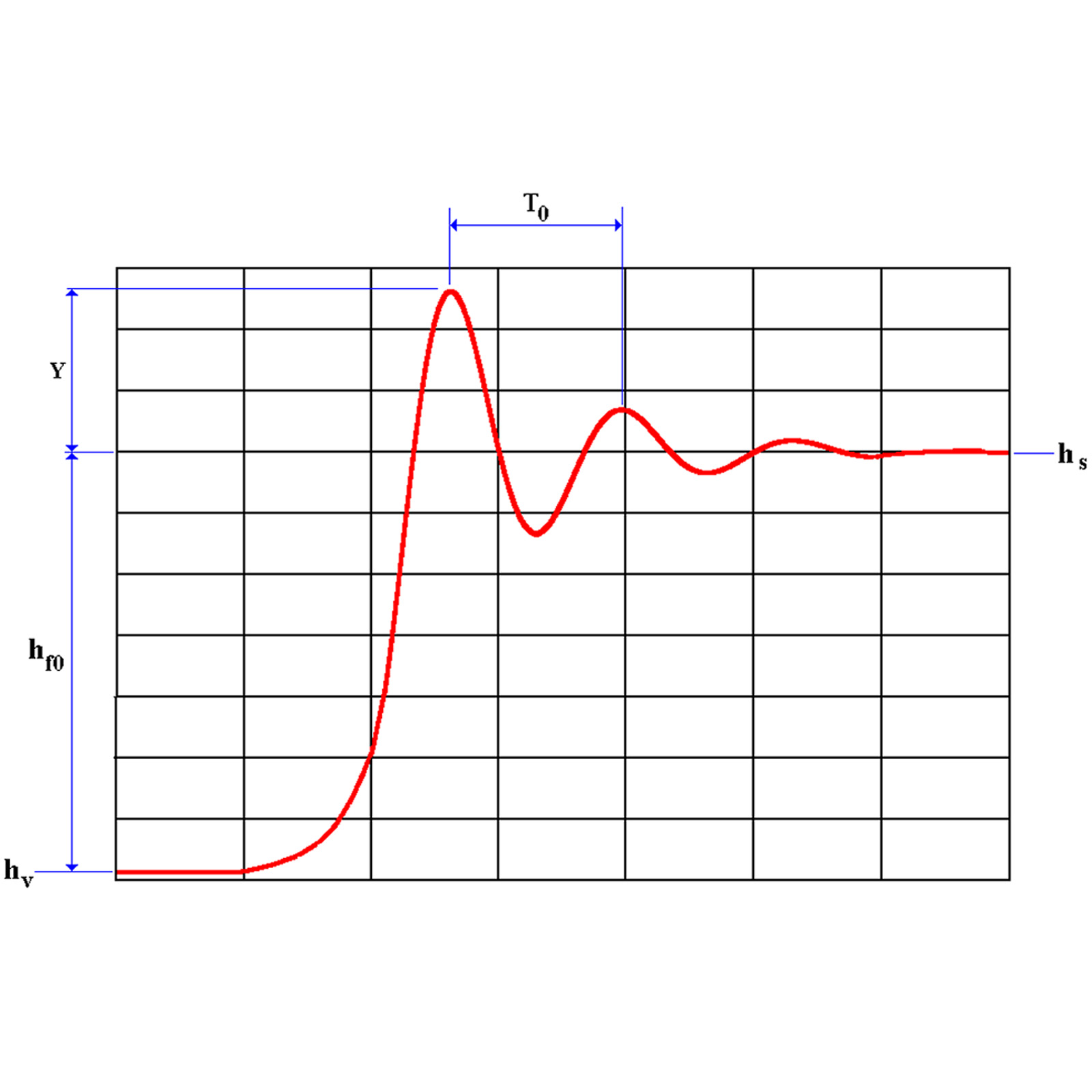
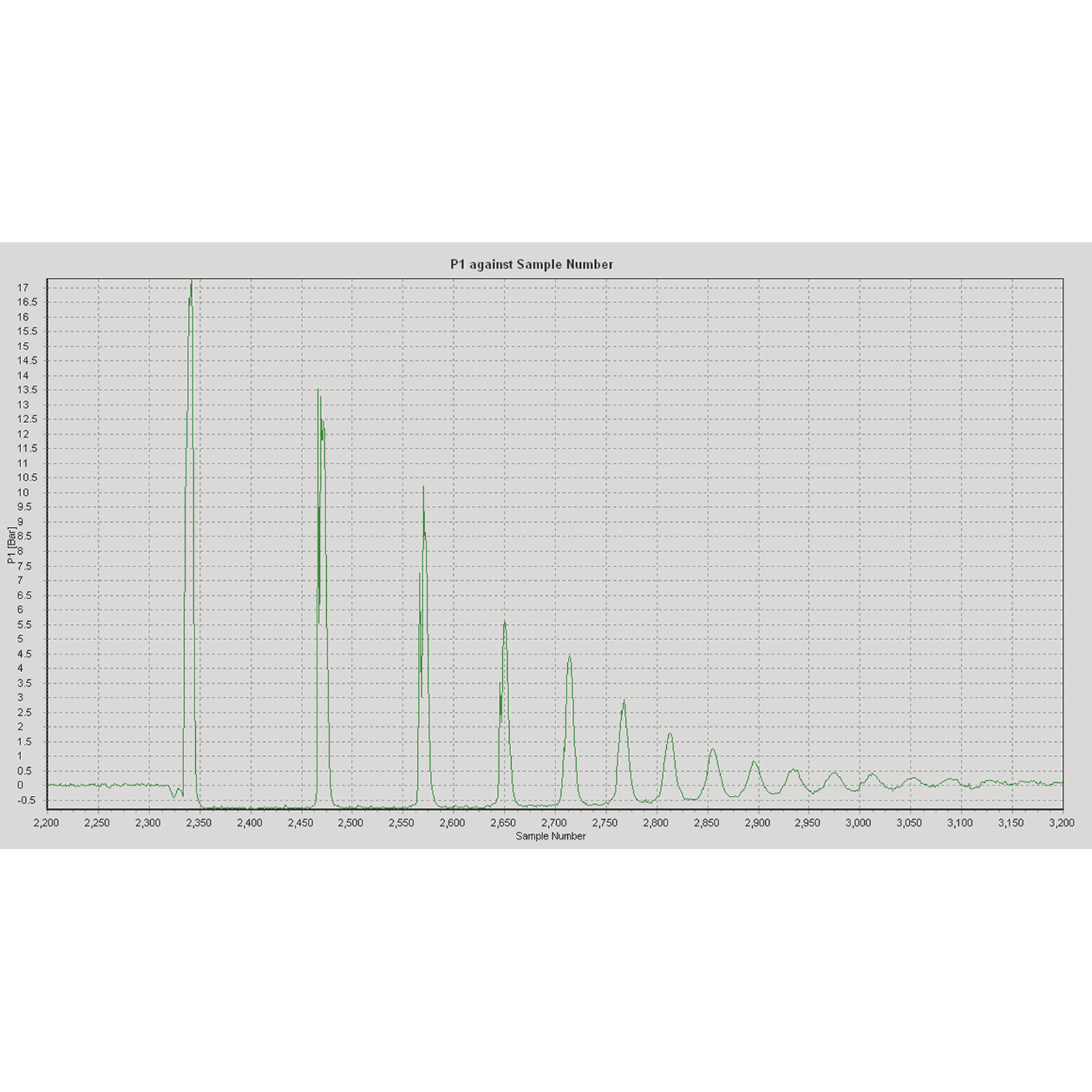
Tappings incorporating electronic pressure sensors are located in the test pipe adjacent to the fast-acting valve and halfway along the test pipe. These sensors measure the high-speed pressure transients inside the pipe as the water hammer travels backward and forward along the test pipe. The time delay between the sensors can be used to determine the speed of sound through the water that is attenuated by the elasticity of the metal pipe wall.
All three pressure sensors are connected to a conditioning unit with USB connection for direct connection to a PC (not supplied by Armfield).
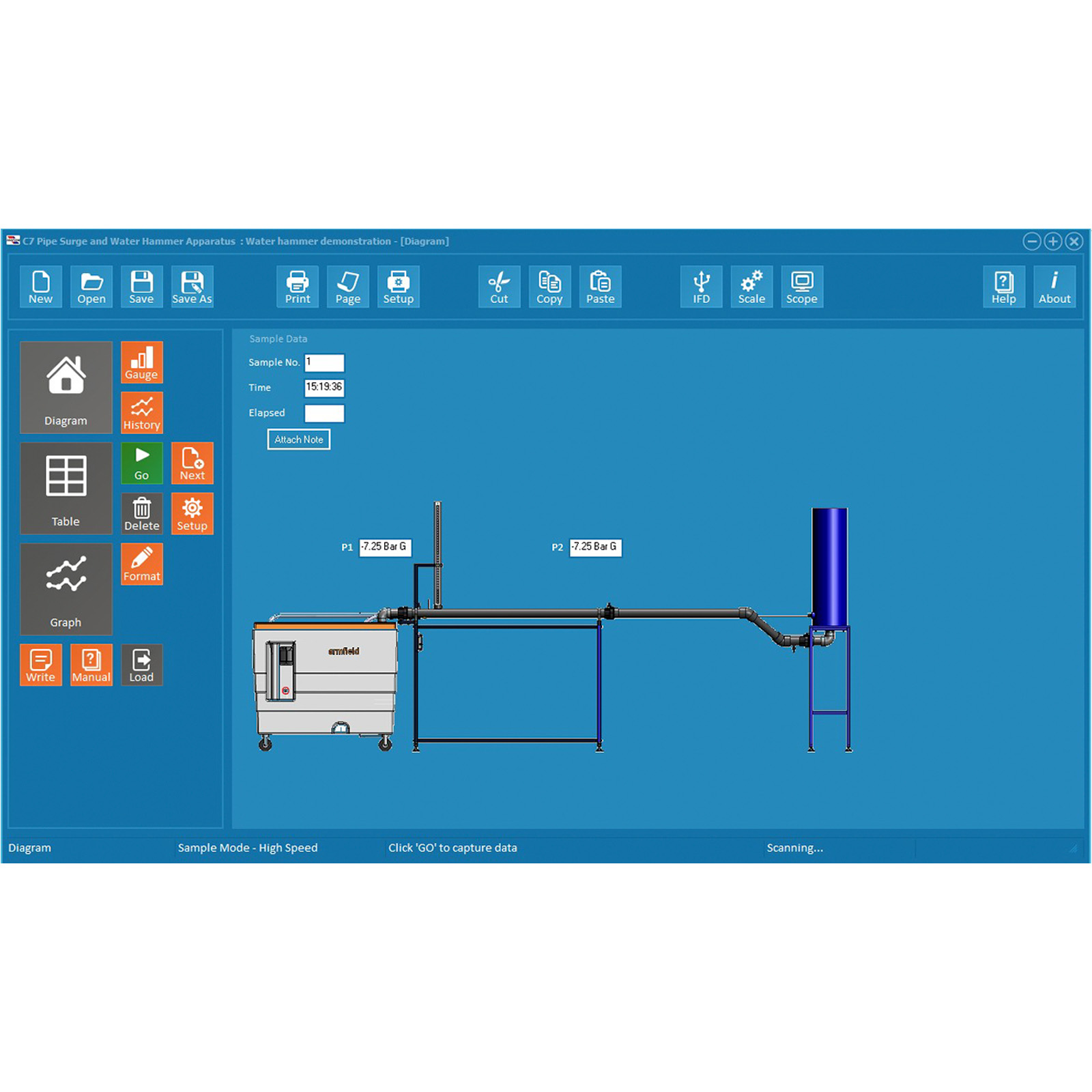
The transient pressure waves can be analysed on the PC (not supplied) using the software supplied. The pressure sensors are powered from the USB port on the PC so no additional power supply is necessary.
Technical Specifications
Features & Benefits
- To demonstrate the phenomenon of pipe surge resulting from a change in velocity of the water flowing along a pipe
- To demonstrate the use of a surge shaft to attenuate any changes in pressure associated with pipe surge and the oscillatory characteristics of water level in a surge shaft
- To determine the characteristics of water hammer
- To demonstrate head loss between the reservoir and the surge shaft due to friction in the pipe
- Interpretation of the traces obtained on the oscilloscope
- Comparison between theoretical and measured pressure profiles associated with water hammer
- Determination of the velocity of sound through a fluid in an elastic pipe
- A free-standing unit designed as an accessory to the Hydraulics Bench to demonstrate the phenomena of pipe surge and water hammer when connected to a Hydraulics Bench
- Includes two separate stainless steel test pipes, both 3m long, constant head tank, slow-acting valve, fast-acting valve etc
- A transparent surge shaft (40mm diameter and 800mm high) with scale enables transient water levels to be observed and timed
- Electronic sensors used to measure pressure transients at two locations in the water hammer test pipe, one adjacent to fast-acting valve and one halfway along the test pipe
- Data logging software included (requires PC, not supplied)
- Pressure transients monitored using a PC via a USB connection from the pressure transducers (requires no external electrical supply)
- Straight metal pipes used, rather than a coiled arrangement, to minimise distortion to the pressure profile
- C1MkII: Compressible Flow Bench
- C3MkII: Multi-pump Test Rig
- C4MkII: Multi-purpose Flume
- C6MkII: Basic Fluid Friction Measurements
- C9: Flow Meter Demonstration Unit
- C10: Laminar Flow Table
- C11MkII: Flow in Pipe Networks
- C15: Computer Controlled Wind Tunnel
- F1-18: Energy Losses in Pipes
- F1-21: Flow Meter Demonstration
- F1-22: Energy Losses in Bends
- A PC running Windows 98 or above with a spare USB port.
- Hydraulics Bench F1-10
PACKED AND CRATED SHIPPING SPECIFICATIONS
C7-MKII
- Volume: 5.0m³
- Gross Weight: 420Kg
C7-MKII-10
- Volume: 3.5m³
- Gross Weight: 260Kg
Length: 3.575m
Width: 0.725m
Height: 1.865m
- C7-MkII
- C7-MkII-10
